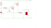
hello, i am assigned to create a physical project starting from the schematics on the left side. my teacher told me that the schematic is incomplete, so the first step is to corect it and then use pads and then send the gerber files to a company to create it. i started reserching it and every schematics i found on the internet about this project had a major diffrence...in my schematics the outputs of the IC 4017 is conecte to 6 resistors...on a number of other similar schematics they are connected to 6 diodes...this is my first project and it is the first time i have to use my electronics knowledge to do something from a tp z and aparently i don`t have much of it
 ...can some one please talk to me about the diffrences on those schematics...can any one shed some light for me on this subject? i will be forever gratefull
 thank you in advance
(sorry for my bad english, i hope you understand what i am talking about ^.^)
thank you in advance
(sorry for my bad english, i hope you understand what i am talking about ^.^)