Maker Pro
Maker Pro

22.2V li-ion battery level indicator?

Hi there, I am building a portable boombox that runs off of a 22.2v li-ion pack I built.

I would like to be able to know if the batteries are dying/dead in a way other than just hearing my audio suddenly start failing.

I looked up battery level indicator circuits and I've gotten a few mixed messages.

Some such as this suggest using two chips.

I've also learned that Zener Diodes are important and this little kit doesn't suggest using chips at all.

I guess it would be cool if it was a 2 color light and green was good, orange=ok, red=bad, but I would also settle for a light just coming on suggesting "low power"

Also none of the kits I've seen mention working with voltages as high as mine. I figure I could do some shoddy math to adjust it to work for me..

But what would be most awesome is if someone here had a straight answer or suggestion for my case.

Thanks a ton!
 
The problem is youre going to need to know the battery voltage when it is dead, for example a fully charged AA battery is 1.55-1.65 volts and dead its 1.25-1.35 typically

without knowing that youre going to be hard pressed to build anything

once you get that, you can use a simple voltage divider to reduce the voltage to a range covered by those options
 
I work with Lithium Ion batteries frequently, I have found that you do NOT want them to drop bellow 2.8 volts per cell. This means your battery will be 'dead' at 16.8 volts. I would say use a 18 volt Zener diode in series with an LED and have it set up in parallel with your circuit.
Just my 2 cents.
-Don
 
Awesome! Thanks guys.

I was going to say the same thing about 18v being the low end.


So if I'm not mistaken it will go something like this:

battery + ------ resistor ----- - 18v Zener + -------+ LED - ---------- - battery

I am still not very good at electronics math, so there are 2 values here that I would love some help with.

What should the wattage rating of the Zener be? 500mw, 1w, 5w? I mean my battery bank with safe exaggeration will be 22v X 3A so thats 66W at full draw....I guess the situation here is that the zener and the led wont draw that much... but I'm not exactly sure how that works.

Also the circuit suggests using a resistor to balance the difference between the zener+led voltage drop and the battery max voltage, so as not to blow the led....Or at least thats how I understand it....Any idea what value this resistor should be for me?


The last little thought is that this circuit is designed to light an LED as long as the battery is "good". But I am looking for something that will let me know when it is BAD. Is there some simple way to switch this around, or perhaps work it so when it goes below the zener rating, it switches to a lower voltage, thus producing a different color on a 2 color LED?

Thanks a million
 

(*steve*)

¡sǝpodᴉʇuɐ ǝɥʇ ɹɐǝɥd
Moderator
Check out this video.

It describes a circuit modification (to a soldering iron) to add a bi-colour LED.

You should start looking at around 12:10.

In your case, the internal transistor shown as part of the existing circuit needs to be part of your circuit.

Also, you need to drive the base of the transistor. You would do this via the 18V zener you've got and a 10k resistor (use a 10k resistor for the other base resistor too.

Use a pair of transistors like BC548's and the resistors in series with the LEDs should be chosen to give whatever current you require (probably 20mA given that the boombox may be used outside). A value of 1k should be fine.

Later in the video he talks about using a mosfet. There's no real point in you doing this. :)
 
I work with Lithium Ion batteries frequently, I have found that you do NOT want them to drop bellow 2.8 volts per cell. This means your battery will be 'dead' at 16.8 volts. I would say use a 18 volt Zener diode in series with an LED and have it set up in parallel with your circuit.
Just my 2 cents.
-Don

this is totally subjective to the cell, I work with batteries (that's what the company I work for makes) and 2.8 is subjective, we keep out batteries between 2-3.6 volts (1.6 I know) but we frequently run 0 volt tests that will discharge cells to 0 volts for 24 hours then recharge them

That indicator system should work for that low voltage limit
 
GreenGiant: True, there are some Li-Ion batteries that run as low as 2.2 volts on the low end, but 0 volts low end? Are you working with Lithium cells or NiCad? I have not heard of lithium cells which it is good to run down all the way. >.> I may have missed something...
Homemadefrog: I just realized how flawed using a single LED would be, no LED I know of runs at 18 volts, you would want four LEDs in series with a hundred ohm resistor to prevent blowing them to smithereens, perhaps even 250 ohms because of the higher voltage.
Good luck!

Li-Ion/Li-Polymer yes, we have one test that runs a "deep discharge" down to 0 volts, discharging for 24 hours down to 0 at 2 amps or more
 
Li-Ion/Li-Polymer yes, we have one test that runs a "deep discharge" down to 0 volts, discharging for 24 hours down to 0 at 2 amps or more

I would expect that to severely diminish the capacity of the cells, do you do this wish just certain test cells or all cells? I'm not sure I would want to buy cells which have had this done to them in the past, I've killed a few LiPo packs by doing this myself. I am rather curious about the chemistry of your company's cells.
Alas, I have brought the thread off track!
-Don


I work for the R&D department so its only on some cells, but typically they bounce back to about 2.4-2.8 volts within an hour of resting
 
I work for the R&D department so its only on some cells, but typically they bounce back to about 2.4-2.8 volts within an hour of resting

Okay, for whatever reason I thought it was a procedure that they did on all the cells... Nevermind my concern then! Although, the ability to rebound the voltage after being fully depleted one time is quite remarkable, it would probably still damage the cells slightly but let you recharge them with normal circuitry rather than needing an extra voltage step down system for normal depleted LiPo batteries. At least I believe that's the goal... I could be totally wrong! Don't hold me to it...
-Don
 
Check out this video.

It describes a circuit modification (to a soldering iron) to add a bi-colour LED.

You should start looking at around 12:10.

In your case, the internal transistor shown as part of the existing circuit needs to be part of your circuit.

Also, you need to drive the base of the transistor. You would do this via the 18V zener you've got and a 10k resistor (use a 10k resistor for the other base resistor too.

Use a pair of transistors like BC548's and the resistors in series with the LEDs should be chosen to give whatever current you require (probably 20mA given that the boombox may be used outside). A value of 1k should be fine.

Later in the video he talks about using a mosfet. There's no real point in you doing this. :)

Hey thanks Steve.

So the internal transistor in that video which does the gate switching is some sort of chip, and what I understand is that that is not only important but something I have to setup in my circuit. Do you have any idea what transistor that should be? Also are you suggesting this chip come before the pair of BC548's, or are you saying the BC548's are the chips I should use instead of the internal transistor in the video?

So the base would be a runoff from the main power positive, going through an 18v zener and a 10k resistor then going to the transistor(s) then going to the LED(s)? I think I understand that the resistor value would determine the current getting to the LED and yes I would be using a 20ma LED, but then what would be the factor that determines whether the current flows through one transistor-resistor-led vs the other? Also can this be done with a bi-color LED?

Sorry if my ignorance frustrates you. Your help has been truly appreciated :)
 

(*steve*)

¡sǝpodᴉʇuɐ ǝɥʇ ɹɐǝɥd
Moderator
So the internal transistor in that video which does the gate switching is some sort of chip, and what I understand is that that is not only important but something I have to setup in my circuit. Do you have any idea what transistor that should be? Also are you suggesting this chip come before the pair of BC548's, or are you saying the BC548's are the chips I should use instead of the internal transistor in the video?

That transistor would need to be part of your circuit, and both could be BC548s (a BC548 is a general purpose small signal NPN transistor. You could use almost anything here it's not critical.

So the base would be a runoff from the main power positive, going through an 18v zener and a 10k resistor then going to the transistor(s) then going to the LED(s)?

yep

I think I understand that the resistor value would determine the current getting to the LED and yes I would be using a 20ma LED, but then what would be the factor that determines whether the current flows through one transistor-resistor-led vs the other?

The collector resistors determine the LED current, the base resistors determine the base current.

Also can this be done with a bi-color LED?

That's exactly what it does use. Specifically it uses one of the reasonably common bicolour LEDs with 2 leads, containing 2 LEDs in inverse parallel (In parallel but pointing in opposite directions)

If I have time I'll draw up the circuit diagram for you a little later because you sound a little confused. If you want to give it a go, please do. You might beat me to it.
Sorry if my ignorance frustrates you. Your help has been truly appreciated :)[/QUOTE]
 

(*steve*)

¡sǝpodᴉʇuɐ ǝɥʇ ɹɐǝɥd
Moderator
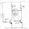
like this:

attachment.php


You should try this out using a variable power supply because it may have quite soft switching characteristics (no may, it will). You could improve that somewhat by adding a resistor between the anode of the zener and ground (this will also affect the switching point)

If you have a 3 terminal dual LED (common anode would be best) you can build this so the colour slowly changes from green, to amber, to red as the battery voltage falls by placing the anode to the +ve rail, and the cathodes to the ends of the 1k resistors.

Because of the 10k base resistor, one LED will always stay very slightly on though.
 

Attachments

  • Scan-120328-0003.jpg
    Scan-120328-0003.jpg
    8.8 KB · Views: 643
like this:

attachment.php


You should try this out using a variable power supply because it may have quite soft switching characteristics (no may, it will). You could improve that somewhat by adding a resistor between the anode of the zener and ground (this will also affect the switching point)

If you have a 3 terminal dual LED (common anode would be best) you can build this so the colour slowly changes from green, to amber, to red as the battery voltage falls by placing the anode to the +ve rail, and the cathodes to the ends of the 1k resistors.

Because of the 10k base resistor, one LED will always stay very slightly on though.

THANK YOU SO MUCH! I will start playing right away!....
 
battery #6 in my pack keeps dying

this is totally subjective to the cell, I work with batteries (that's what the company I work for makes) and 2.8 is subjective, we keep out batteries between 2-3.6 volts (1.6 I know) but we frequently run 0 volt tests that will discharge cells to 0 volts for 24 hours then recharge them

That indicator system should work for that low voltage limit

Hey guys, just wanted to once again thank you for all your input. There has been another little puzzle boggling my somewhat novice mind, and it has to do with the battery pack itself, which is why I am sort of addressing you GreenGiant (and all battery pros).

I purchased this 22.2V 6cell PCB from ebay to monitor my 6 cells. I wired everything according to the diagram and general understanding of batteries. Everything was working fine, no sparks, no overheating, and all the voltages across each battery as well as the total pack voltage were fine. That stayed true until several hours of connecting using it to play music on my amp. At this point I noticed somewhat of a lack of power in my unit so I checked the charge of the battery. All the cells were fine except for battery #6 which was totally dead!

I figured it was a bad cell so I switched it with another. Same result! I did this twice!
Then I purchased a new board (same one) and same result!

My last assumption is that there is some fault in the design of this board. But being such a novice I had to just ask if any battery pros have heard of such an issue. If you have I would love to know what you think is going on.

Thanks!
 

(*steve*)

¡sǝpodᴉʇuɐ ǝɥʇ ɹɐǝɥd
Moderator
Is the last cell really dead? Did you measure the voltage with a multimeter?

It's too much of a coincidence that the same battery seemingly died on 2 packs.

I would be looking carefully at the monitor device. Perhaps measuring its current draw would be a good idea.
 
Hi Steve, sorry this comes so late, its been a long interesting adventure getting this little level indicator working and I cannot thank you enough for all your help, I am learning a ton.

The good news is that I got the original bicolor 2-lead LED circuit working and it performs just as you described!

Of course just as the initial joy wore off I began to see the downsides of a slowly changing bicolor LED in that at some point the light will be inbetween and will seem off...which would be confusing.

So I ordered some 3-lead common anode LED's and hooked one up the way you described.

I started using a 5v zenner and a 3v supply and it seemed to work, it started red. then I went to 6v and it turned a bit orange. But then when I went to 10v it burned out. I tried again, same thing. Then I realized I burned out one of my little transistors in the last burnout so I changed it. I continued destroying many little components only to find that no matter what, when I went above 6v the system would overheat really fast and blow the LED and or the transistor (the one with the base running to the collector of the other transistor via 10kresistor). I eventually gave up, reset it back to the bicolor 2-lead setup and it worked again with no extra heat. I also went ahead and just used the multimiter as a standin for the bi-color 3-led setup and the voltage seemed to make sense, switching polarity and all, and when I did this nothing heated up at all.

Any ideas why the common anode LED setup is heating up/blowing? Or solutions?

Thanks a million
 
This is probably the stupidest question to ask, but what's the resistor value of the resistor between the red LED's cathode and whatever is driving it? Is there one?
-Don
 

(*steve*)

¡sǝpodᴉʇuɐ ǝɥʇ ɹɐǝɥd
Moderator
So I ordered some 3-lead common anode LED's and hooked one up the way you described.

Did I recommend something with a common anode LED? I'll have another look, but you might have to point me to what I recommended.
 
Top