Maker Pro
Maker Pro

2-stage Class A Amplifier: Gains(voltage and power)

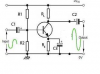
Hi there! I am a electronics technology student, i would like to ask about how to calculate the power gain and voltage gain for a 2 stage class A amplifier. And what transistor i should use and what will be my frequency range for my audio amp.
 
Well that would depend on the use of the amp.
20 - 20,000Hz is the general audio frequencies.
Or for low bass 20Hz and lower.

Martin
 
Well that would depend on the use of the amp.
20 - 20,000Hz is the general audio frequencies.
Or for low bass 20Hz and lower.

Martin
Sorry for my delay response. Ah, yes i used 20-20kHz. Thanks for affirming the freqs . Can u cite transistors that is suitable for Class A Amps? Sir Martin? :)
 
Hi Mark,
I couldn't possibly say.
What circuit have you designed?
A small signal transistor to a mosfet will do.
A BJT will require about 0.7v and a mosfet about 3v or more.
If you upload the circuit diagram I am sure somebody will be able to help you.

Martin
 
You don't want each stage to be more than about 50, otherwise you will get a lot of instability - called "motorboating."
When we talk about a "gain of 50" we mean voltage gain for the first stage - called the pre-amplifier stage and a "gain of 50" - meaning a current gain for the output stage.
 
Mark, stop calling me sir! please:)
Pretty much any transistor. The 2N2222 will be just fine.
It's the circuit that makes an amp or a switch. Not the transistor. The transistor can be used for both.

Martin
 

CDRIVE

Hauling 10' pipe on a Trek Shift3
Sir Martin :p has given you good advice but I'm curious.. You didn't state what your input source or output load will be. Did your instructor specify these?

Chris
 
@Martaine2005 Sorry for calling you Sir, SIR MARTIN! :p It is my way of respecting! :) Anyways thanks a lot for the clarification

@CDRIVE Sir? My instructor only told me to design an amp, a 2 stage, he even told me that a 3stage is good also. :) Tho i dont really like to make a 3 stage since the 3rd stage will be an AB amp as i was told. For now sir, i've been feeding signals to it, using signal gen.
My prob is theres no output tho the transistor is working fine( i got 0.7 Vdrp in Vbe ) . What wrong with my design sir?
 

CDRIVE

Hauling 10' pipe on a Trek Shift3
@CDRIVE Sir? My instructor only told me to design an amp, a 2 stage, he even told me that a 3stage is good also. :) Tho i dont really like to make a 3 stage since the 3rd stage will be an AB amp as i was told. For now sir, i've been feeding signals to it, using signal gen.
My prob is theres no output tho the transistor is working fine( i got 0.7 Vdrp in Vbe ) . What wrong with my design sir?

Hard to say without some info. If this is your schematic there's nothing wrong with the physical design but the component values can be all wrong. Please fill in the component values so we'll know. Are you monitoring the output on a scope?
21352-a0fa6ee71888709af18f3b9143bc8b6f.jpg

Chris
 
Hard to say without some info. If this is your schematic there's nothing wrong with the physical design but the component values can be all wrong. Please fill in the component values so we'll know. Are you monitoring the output on a scope?
21352-a0fa6ee71888709af18f3b9143bc8b6f.jpg

Chris
Yes i am sir, im using a software called Multisim :) Is this a reliable?

By the way Sir Chris, here is my design ( im not confident with the values tho, this is the result of my solutions :()
 

Attachments

  • Untitled.png
    Untitled.png
    9.5 KB · Views: 93
Top