Maker Pro
Maker Pro

120vac to 0-90vdc motor drive

Hello I need help repairing a 0-90vdc drive. I have powered it up and I get voltage at output to motor but it only varies from 65-90vdc instead of 0-90vdc. I tested pots and some other voltage areas.... I have a schematic I'll post.

josh47_schematic_cropped.jpg
Moderators note : cropped and rotared picture
 

Attachments

  • Screenshot_2021-02-09-17-55-56-760.jpg
    Screenshot_2021-02-09-17-55-56-760.jpg
    106.9 KB · Views: 40
Last edited by a moderator:
Think there is more to the diagram.
Lower and top centre shows termination for field coils.
Where are you taking your measurements from..?
 
Ty for reply
that's the only diagram I know off the feild connections just go to terminal strip on PCB but never were used.
I took my measurements from A+ A-. Armature (+) and( -) which is were you should get you're variable DC. I think somthing might be up with the opamp or opto triac Ic ?
 
But the motor would require both armature and field........has this been modified or is the motor permanant magnet..?

Do you have control voltage...12v..?
Your diagram does not show any power supply for the former.
Been a while since I've seen unijunction transistors used...must be old as...??
 
No not modified, I'm repairing for a friend and have repaired others but this one's giving me trouble...from what I've seen on other repairs every drive never had feild wired up, Just line voltage in(120vac) and A1 & A2 out to motor. So yeah must be permanent magnetic. Yes it seems I have control voltage. Checking pins 4 and 11 of op amp has power. I'll check later on to verify its a solid 12v I changed out the op amp out for 1 laying around so I'm unsure of the condition it was in... ordered some new ones to try. Going to look into optocoupler later on today. Thanks again for looking into this
 
If it is a series DC motor, then the field is energized by the diode rectifiers (bridge) on the AC.

Is the problem that the motor is running when it shouldn't be, i.e. when the speed pot is set for zero?
 
Last edited:
No the issue is I have no variable speed. But I've checked the potentiometer and it's fine. On others I've fixed I could check the output with a meter adjust speed and see the voltage change. For this one I'm getting 65vdc constant at output and when I adjust pot it will vary from 65 to 90. It should read 0v when pot is turned completely down. At least for the other ones I'm fixed. Maybe this one needs a loaf connected?
 
So is there a motor in the circuit that is running at a constant speed and won't slow down?

If there is no motor in the circuit then you have no feedback in the current loop and the controller will keep trying to increase the speed (raise the voltage) in order to detect current thru the motor armature.

Not really sure what your problem is here--does the motor spin or not, does it vary speed while spinning or not, etc...?
 
Okay so, I don't have a 90v motor on me to hook up but the last drive I fixed didn't need one. I could just used a Meter to test voltage at output terminals while I turned the speed pot up and down. If this is the case of needing a motor hooked up to verify is there any way I could hook up a dummie load ?
 
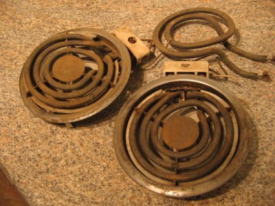
Can you get your hands on some stove heating elements from the thrift store or a home recycling store, etc? You could use that as the load and it would provide the feedback current. It looks like there is a 10A fuse on the 120VAC, so it is meant to operate about a 1.5 HP or smaller motor. The current limit can be set for about 20A max on the DC motor current, so if you get a stove eye with about 5 to 10Ω resistance it should work. You can add 2 or more eyes in series to increase the R and reduce the load current. They will glow and get hot so use caution not to burn down your workbench.

545836397_tp.jpg
 
I believe that is a series of drives like KB etc, they supply drives for P.M. and wound field included in the same drive., the circuitry is provided for both, most are P.M. field now.
M.
 
Would a scr variable voltage regulator and a large full bridge rectifier accomplish the same task as the drive? Other than being able to set min/max ir comp and current limiting...
 
I took some scope reading from the gate of the 2n6027 transistor maybe this will help still looking for a heating element. pic of speed pot a low setting.
josh47_scope picture_cropped.jpg

Moderators note : cropped and rotated image
 

Attachments

  • Screenshot_2021-02-11-17-52-21-838.jpg
    Screenshot_2021-02-11-17-52-21-838.jpg
    89.5 KB · Views: 9
Last edited by a moderator:
With no load i might expect to see the gate of the transistor being switched at 2x the AC line frequency, so 120 Hz in US or 100 Hz in EU. Not sure whats the time base of your scope.

Also the gate voltage would be about 6 VDC with respect to ground.

What does it look like when the speed pot is set toward the high end?
 
Last edited:
Here is a pic of the speed spot set,high gate measurement

josh47_scope picture2_cropped.jpg

Moderators note : Please use the essential parts of the picture, picture cropped
 

Attachments

  • Screenshot_2021-02-12-10-14-32-054.jpg
    Screenshot_2021-02-12-10-14-32-054.jpg
    90.1 KB · Views: 4
Last edited by a moderator:
Looks good to me, the dc level (6V) was raised as needed to create the signal to run faster, and there are wide negative-going pulses at the 2x line frequency as expected.

This is driving the optocoupler which drives the gates of the L512F triac module and causes the voltage to increase up to 90V as you measured.

What's the history of this controller--do you know that it was bad or are you just testing it? i suspect it should work with a motor connected unless there is an issue in feedback circuit to the op amp.

Thank you to the modulator for adjusting the photos.
 
I was told it was bad, but it sucks because I don't have a motor to test with..other models I've repaired I was able to verify it was working with a multimeter at the armature output terminals and check for voltage regulation.
 
When I recieved the DC drive after checking armature output the only component I changed out was the lm324 opamp but this did not make any difference from what I see. I need to get my hands on a element or somthing to simulate a motor connected.
 
Why an element? Why not a motor?.
You can find motors in broken devices all day.
Printers, toy cars, trains, VCRs, washing machines, drills, sanders, battery vacuum hoovers, battery fans.
Also a vehicle breaking yard: windscreen wiper motor, windscreen washer motor, electric windows, mirrors, seats etc.
But an element can also be a toaster, hair dryer, sandwich maker, hot air gun etc etc etc. Use your imagination.

Martin
 
Top