Maker Pro
Maker Pro

Need help to repair computer power supply

Hi,

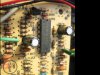
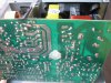
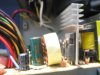
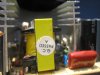
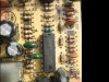
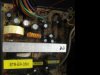
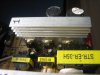
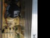
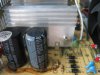
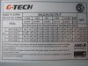
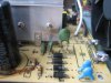
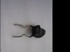
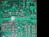
My desktop pc Pentium 4 power supply recently flashed a bright spark and some smoke upon pressing switch on the pc; then the pc not able to turn on. After unplug the wall power cable, I tried open the power supply case (G-TECH SFX-500) and noticed the thermistor NTC 5D-9 is blown and glass fuse 5A/250V shorted. The power supply is a cheap China made model with no schematic upon google search and I suspect it is a 250-320 watt power supply.

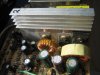
Since I didn't notice any other burnt or any other darken area, I just replaced the thermistor with SCK 053 and a glass fuse 6.3A/250V (I bridge solder this to the blown fuse) salvaged from a junk board. I admit it is a huge mistake to rush and switch on the supply as the fuse flashed a bright spark but nothing happen to the newly replaced thermistor SCK 053.

I hope this does not destroy any other vital component and plan to repair the power supply to a working state instead of throwing to the garbage. The question is whether i can use "series light bulb" to diagnose the power supply and how do I connect "series light bulb" in this case. On hand the equipment I have is a 40 watt soldering iron, a desolder pump, an analog multimeter, a digital multimeter and a capacitor meter.

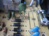
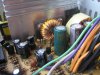
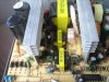
Attached few photos of the power supply and any help in repairing to working condition is greatly appreciated. :)
 

Attachments

  • IMG_0131-fuse.JPG
    IMG_0131-fuse.JPG
    45.8 KB · Views: 1,083
  • IMG_0132-thermistor.JPG
    IMG_0132-thermistor.JPG
    17.3 KB · Views: 750
  • IMG_0133-fuse.JPG
    IMG_0133-fuse.JPG
    39.9 KB · Views: 1,058
  • IMG_0134-output caps.JPG
    IMG_0134-output caps.JPG
    53.4 KB · Views: 627
  • IMG_0130-label.JPG
    IMG_0130-label.JPG
    58.4 KB · Views: 626
  • IMG_0135-top.JPG
    IMG_0135-top.JPG
    54.4 KB · Views: 2,775
  • IMG_0137-track.JPG
    IMG_0137-track.JPG
    49.6 KB · Views: 516
  • IMG_0138-top.JPG
    IMG_0138-top.JPG
    37.4 KB · Views: 475
  • IMG_0141-output.JPG
    IMG_0141-output.JPG
    41.2 KB · Views: 486

(*steve*)

¡sǝpodᴉʇuɐ ǝɥʇ ɹɐǝɥd
Moderator
I would be checking the power semiconductors for shorts.

The most likely is a transistor on the heatsink on the left of this image:

10482d1384849704-need-help-repair-computer-power-supply-img_0135-top.jpg


There's several, start with the biggest one :)

If there's not one shorted there, look at the devices (typically diodes) on the right hand heatsink.

The third thing to do is to carefully examine the chip on the lower right corner of this image. Make sure nothing looks amiss there.

Oh, it's also possible that one of the 4 diodes in the bridge on the lower left corner has shorted. They're probably the easiest to test. Do them first.

There are capacitors in this circuit that can give you a nasty shock, and fry your meter, so leave it sit for a couple of hours after you last plugged it in and handle it as if it was live. Check for voltages across the big 400V capacitors before you do anything else. Anything under about 10V means you're good to go.

In all cases (other than the 8 pin chip) get your multimeter and measure the resistance both ways on each pair of terminals. Be suspicious if you get a low resistance (under 100 ohms) in *both* directions. Let the resistance reading stabilize. If it's rising and goes over 100 ohms, leave it. It won't come back down.

If you remain suspicious about any part, you will then need to remove it from the circuit and test it again.
 
Hi Steve,

As your advice, I use multimeter measure resistance both ways to check for
low resistance under 100ohms and put my probe on the track side as the component
side is a bit cramped. The measurement I got from transistor on left heatsink (label 1) is between 2 to 50 ohms as well as diodes/transistor on right hand heatsink (i label 2).
Are the transistor shorted ? Refer photos of heatsink 1 & 2.


When I measured resistance of the 4 diodes on lower left (B01 to B04) with an analog multimeter, the meter just swings halfway on both ways. Are the diodes shorted ?
or is it more accurate to measure after desolder one leg of the diode ?

When i examine closely at the two pcs 8 pin chip on lower right, they seems to be nothing
amiss, no burn or dent or bulge. I attached photos as chip 1 & chip2.

Any further help and guide is appreciated.
Thank you and regards. :)
 

Attachments

  • IMG_0144-chip2.JPG
    IMG_0144-chip2.JPG
    48.8 KB · Views: 468
  • IMG_0149-track.JPG
    IMG_0149-track.JPG
    61.6 KB · Views: 391
  • IMG_0147-heatsink2side.JPG
    IMG_0147-heatsink2side.JPG
    40.8 KB · Views: 426
  • IMG_0148-heatsink1side.JPG
    IMG_0148-heatsink1side.JPG
    35.9 KB · Views: 479
  • IMG_0143-chip1.JPG
    IMG_0143-chip1.JPG
    49 KB · Views: 443
  • IMG_0150-top.JPG
    IMG_0150-top.JPG
    29.7 KB · Views: 344
  • IMG_0152-heatsink1.JPG
    IMG_0152-heatsink1.JPG
    41.2 KB · Views: 350
  • IMG_0151-heatsink2.JPG
    IMG_0151-heatsink2.JPG
    47.1 KB · Views: 416

(*steve*)

¡sǝpodᴉʇuɐ ǝɥʇ ɹɐǝɥd
Moderator
As your advice, I use multimeter measure resistance both ways to check for
low resistance under 100ohms and put my probe on the track side as the component
side is a bit cramped. The measurement I got from transistor on left heatsink (label 1) is between 2 to 50 ohms as well as diodes/transistor on right hand heatsink (i label 2).
Are the transistor shorted ? Refer photos of heatsink 1 & 2.

If you can read what is printed on this component, tell us, and indicate how you measured the low resistance.

For example, you can number the leads 1, 2, and 3 from left to right as you read the part number on the device. Then tell us (say) that you got a reading of 15 ohms between pin 1 and 3 with the leads one way and 12 ohms the other way.

If your meter has a diode test function use that as well. This generally gives the voltage drop, so it might read 621 in one direction and 780 in the other -- this is typically only found on digital multimeters.

When I measured resistance of the 4 diodes on lower left (B01 to B04) with an analog multimeter, the meter just swings halfway on both ways. Are the diodes shorted ? or is it more accurate to measure after desolder one leg of the diode ?

It seems unlikely they are shorted. Yes, you will get a more accurate reading if you lift one end of the component. Initially test only one diode because they all sound similar. You are expecting to see a significant difference when you read the resistance one way vs. the other.

When i examine closely at the two pcs 8 pin chip on lower right, they seems to be nothing
amiss, no burn or dent or bulge. I attached photos as chip 1 & chip2.

I agree. There's nothing obvious I can see either.

Any further help and guide is appreciated.
Thank you and regards. :)[/QUOTE]
 
Hi Steve,

Sorry, earlier on the reading was taken from setting digital meter to ohm reading. My apology to misled as I agree due to my inexperience and I am willing to learn more.

On my digital meter diode setting, I am taking the component reading from left to right (like pin 1,2,3) and - as black negative probe while + as red positive probe. Also I listed down the component part number and each reading from the meter.

On heat sink label "1" nearest the two big caps:
component 1 nearest to fan (on board as Q2) part no. WXDH 705 C5027-R

-1 & +2 = 711 ( here pin 1 to black probe & pin 2 to red probe = 711 on diode reading)
-1 & +3 = 704 ( here pin 1 to black probe & pin 3 to red probe = 704 on diode reading)
-2 & +1 = 559 so forth........
-2 & +3 = 8
-3 & +1 = 567
-3 & +2 = 8

component 2 middle item (on board as Q01) part no. F51 J13007-2

-1 & +2 = 2 ( here pin 1 to black probe & pin 2 to red probe = 2 on diode reading)
-1 & +3 = 2 ( here pin 1 to black probe & pin 3 to red probe = 2 on diode reading)
-2 & +1 = 2 so forth........
-2 & +3 = 1
-3 & +1 = 2
-3 & +2 = 1

component 3 last item (on board as Q02) part no. F946 E13007-2

-1 & +2 = 2 ( here pin 1 to black probe & pin 2 to red probe = 2 on diode reading)
-1 & +3 = 2 ( here pin 1 to black probe & pin 3 to red probe = 2 on diode reading)
-2 & +1 = 2 so forth........
-2 & +3 = 2
-3 & +1 = 2
-3 & +2 = 1

On heat sink label "2" nearest to the two coils:
component 1 (on board as D33) part no. MOSPEC S20C40C

-1 & +2 = 72 ( here pin 1 to black probe & pin 2 to red probe = 72 on diode reading)
-1 & +3 = 1 ( here pin 1 to black probe & pin 3 to red probe = 1 on diode reading)
-2 & +1 = 67 so forth........
-2 & +3 = 67
-3 & +1 = 2
-3 & +2 = 72

component 2 (on board as D31) part no. MOSPEC F12C20C

-1 & +2 = 262 ( here pin 1 to black probe & pin 2 to red probe = 262 on diode reading)
-1 & +3 = 1 ( here pin 1 to black probe & pin 3 to red probe = 1 on diode reading)
-2 & +1 = 262 so forth........
-2 & +3 = 262
-3 & +1 = 1
-3 & +2 = 262

component 3 (on board as D30) part no. MOSPEC S15D40C

-1 & +2 = 51 ( here pin 1 to black probe & pin 2 to red probe = 51 on diode reading)
-1 & +3 = 1 ( here pin 1 to black probe & pin 3 to red probe = 1 on diode reading)
-2 & +1 = 50 so forth........
-2 & +3 = 50
-3 & +1 = 1
-3 & +2 = 51

I hope the above readings are not too long and confusing to understand.
After your review of those readings, appreciate if you can shed some light on which
component is suspect to be faulty and need replacement.

In addition, when I measured resistance of the 4 diodes on lower left (B01 to B04) with the same digital multimeter at diode setting, all I get is 1 & 2 (other way) or 1 & 1 (other way).
Is this meaning too low resistance or shorted diode ?
By this weekend, I will try desolder one leg of the diode and do some reading; then inform you of any new discovery.

Thanks again for the many guidance and hope for continue support.
 

(*steve*)

¡sǝpodᴉʇuɐ ǝɥʇ ɹɐǝɥd
Moderator
I hope the above readings are not too long and confusing to understand.
After your review of those readings, appreciate if you can shed some light on which
component is suspect to be faulty and need replacement.

Yeah, I will admit that I'm not 100% certain about your readings.

Sorry, earlier on the reading was taken from setting digital meter to ohm reading. My apology to misled as I agree due to my inexperience and I am willing to learn more.

No problems.

On my digital meter diode setting, I am taking the component reading from left to right (like pin 1,2,3) and - as black negative probe while + as red positive probe. Also I listed down the component part number and each reading from the meter.

And it certainly sounds like you've done *exactly* what I've asked.

On heat sink label "1" nearest the two big caps:
component 1 nearest to fan (on board as Q2) part no. WXDH 705 C5027-R

To me, this sounds like a 2SC5027. Can you take a quick look at the datasheet to see if the drawing of the device matches what it looks like?

-1 & +2 = 711 ( here pin 1 to black probe & pin 2 to red probe = 711 on diode reading)
-1 & +3 = 704 ( here pin 1 to black probe & pin 3 to red probe = 704 on diode reading)
-2 & +1 = 559 so forth........
-2 & +3 = 8
-3 & +1 = 567
-3 & +2 = 8

My initial assumption is that this is the main high voltage chopper transistor. And a short circuit failure of this will cause the symptoms you report.

Some of the readings you report are very odd. The readings you report as "8" are particularly interesting.

I'm thinking that we need to either look at the circuit around this to see why these odd readings could be generated, or maybe pull it out and test it out of circuit. (but don't do it just yet).

component 2 middle item (on board as Q01) part no. F51 J13007-2
This looks like it could be a PJ13007. Again, please check the datasheet to see if it looks physically like the same component.

-1 & +2 = 2 ( here pin 1 to black probe & pin 2 to red probe = 2 on diode reading)
-1 & +3 = 2 ( here pin 1 to black probe & pin 3 to red probe = 2 on diode reading)
-2 & +1 = 2 so forth........
-2 & +3 = 1
-3 & +1 = 2
-3 & +2 = 1

These are really weird readings. It would be interesting to see what the resistance readings are on these combinations of pins too.

This is also a high voltage transistor (if my assumption about part number is right).

If I'm reading your measurements correctly, this looks shorted.

(What does the meter read on the diode test when the probes are shorted, and open respectively?)

component 3 last item (on board as Q02) part no. F946 E13007-2

This may be a MJE13007. (Again, check the datasheet for the package).

-1 & +2 = 2 ( here pin 1 to black probe & pin 2 to red probe = 2 on diode reading)
-1 & +3 = 2 ( here pin 1 to black probe & pin 3 to red probe = 2 on diode reading)
-2 & +1 = 2 so forth........
-2 & +3 = 2
-3 & +1 = 2
-3 & +2 = 1

Theses seem to be very similar readings and again look like a shorted transistor.

Now on the second heatsink I'm expecting to see a collection of double diodes.

On heat sink label "2" nearest to the two coils:
component 1 (on board as D33) part no. MOSPEC S20C40C

This looks like an S20C40! (not surprising). Again check the datasheet for the package.

That package is called TO-220 and it appears all the devices are in this package, right?

-1 & +2 = 72 ( here pin 1 to black probe & pin 2 to red probe = 72 on diode reading)
-1 & +3 = 1 ( here pin 1 to black probe & pin 3 to red probe = 1 on diode reading)
-2 & +1 = 67 so forth........
-2 & +3 = 67
-3 & +1 = 2
-3 & +2 = 72

component 2 (on board as D31) part no. MOSPEC F12C20C

And the datasheet for that one.

-1 & +2 = 262 ( here pin 1 to black probe & pin 2 to red probe = 262 on diode reading)
-1 & +3 = 1 ( here pin 1 to black probe & pin 3 to red probe = 1 on diode reading)
-2 & +1 = 262 so forth........
-2 & +3 = 262
-3 & +1 = 1
-3 & +2 = 262

component 3 (on board as D30) part no. MOSPEC S15D40C

datasheet. And this one seems to be in a different and larger package, right?

-1 & +2 = 51 ( here pin 1 to black probe & pin 2 to red probe = 51 on diode reading)
-1 & +3 = 1 ( here pin 1 to black probe & pin 3 to red probe = 1 on diode reading)
-2 & +1 = 50 so forth........
-2 & +3 = 50
-3 & +1 = 1
-3 & +2 = 51

These three devices have a similar pattern of readings. In all cases, pins 3 and 1 are likely connected together on the board, and none have any pattern suggesting a short.

In addition, when I measured resistance of the 4 diodes on lower left (B01 to B04) with the same digital multimeter at diode setting, all I get is 1 & 2 (other way) or 1 & 1 (other way).
Is this meaning too low resistance or shorted diode ?
By this weekend, I will try desolder one leg of the diode and do some reading; then inform you of any new discovery.

It is possible that you have one or more shorted diodes, and/or the second and/or the third transistor above might be shorted.

It might be a good idea to lift one end of each of the diodes and measure them independently.

THEN (while the diodes are out of circuit) repeat the readings on the three transistors on the first heatsink

Thanks again for the many guidance and hope for continue support.

No problems.

With luck, only the diodes and/or transistors are at fault.
 
Hi Steve,

This morning (Saturday 23 Nov 2013), I desolder one leg of the diodes (position on board as BD2,BD1,BD4 & BD3) refer photo of img 0155 on diode BD2 as nearest to thermistor SCK053.
Then by setting the digital meter to diode test I got the following readings:

On diode position BD2 (top nearest to thermistor),red probe to left diode while black probe to right side reads 2, then reverse probe then get reading 2.
On diode position BD1,red probe to left diode while black probe to right side reads 1 (over limit), then reverse probe then get reading 595.
On diode position BD4,red probe to left diode while black probe to right side reads 590, then reverse probe then get reading 1 (over limit).
On diode position BD3 (last line),red probe to left diode while black probe to right side reads 2, then reverse probe then get reading 2.

For info, all the four diodes show part No. as RL 207 HG.

Your suggestion of the datasheet shows along heat sink 1, those components WXDH 705 C5027-R looks like 2SC5027, F51 J13007-2 looks like PJ13007, and F946 E13007-2 looks like MJE13007-M. Physically they looks similar.

This is also the same physical look for components along heat sink 2, MOSPEC S20C40C looks like S20C40, as well as MOSPEC F12C20C & MOSPEC S15D40C (slightly in larger package).

It might be a good idea to lift one end of each of the diodes and measure them independently.

As you mentioned "Then (while the diodes are out of circuit) repeat the readings on the three transistors on the first heatsink " which I did with the following readings:

On heat sink label "1" nearest the two big caps:
component 1 nearest to fan (on board as Q2) part no. WXDH 705 C5027-R

-1 & +2 = 557 ( here pin 1 to black probe & pin 2 to red probe = 557 on diode reading)
-1 & +3 = 564 ( here pin 1 to black probe & pin 3 to red probe = 564 on diode reading)
-2 & +1 = 708 so forth........
-2 & +3 = 8
-3 & +1 = 702
-3 & +2 = 8

component 2 middle item (on board as Q01) part no. F51 J13007-2

-1 & +2 = 2 ( here pin 1 to black probe & pin 2 to red probe = 2 on diode reading)
-1 & +3 = 2 ( here pin 1 to black probe & pin 3 to red probe = 2 on diode reading)
-2 & +1 = 2 so forth........
-2 & +3 = 2
-3 & +1 = 2
-3 & +2 = 2

component 3 last item (on board as Q02) part no. F946 E13007-2

-1 & +2 = 2 ( here pin 1 to black probe & pin 2 to red probe = 2 on diode reading)
-1 & +3 = 2 ( here pin 1 to black probe & pin 3 to red probe = 2 on diode reading)
-2 & +1 = 2 so forth........
-2 & +3 = 2
-3 & +1 = 2
-3 & +2 = 2

You also inquired on " What does the meter read on the diode test when the probes are shorted, and open respectively?" to which I set the meter to diode and test on the burnt 5A fuse, and the meter reads 1 (being over limit).

On another note, for curiosity does the "series light bulb trick" using a 100w light bulb in series with the mains helps in detecting any faulty component ? especially to protect any more damage to other component. Just eager to know.

Thanks for taking the time and patience to explain each step.
 

Attachments

  • IMG_0155-diode.JPG
    IMG_0155-diode.JPG
    30.1 KB · Views: 319

(*steve*)

¡sǝpodᴉʇuɐ ǝɥʇ ɹɐǝɥd
Moderator
On diode position BD2 (top nearest to thermistor),red probe to left diode while black probe to right side reads 2, then reverse probe then get reading 2.
On diode position BD1,red probe to left diode while black probe to right side reads 1 (over limit), then reverse probe then get reading 595.
On diode position BD4,red probe to left diode while black probe to right side reads 590, then reverse probe then get reading 1 (over limit).
On diode position BD3 (last line),red probe to left diode while black probe to right side reads 2, then reverse probe then get reading 2.

OK, BD2 and BD3 have failed short circuit. I would replace all 4 diodes.

For info, all the four diodes show part No. as RL 207 HG.
Here is the datasheet. That's a 1000V 2A diode.

Your suggestion of the datasheet shows along heat sink 1, those components WXDH 705 C5027-R looks like 2SC5027, F51 J13007-2 looks like PJ13007, and F946 E13007-2 looks like MJE13007-M. Physically they looks similar.

This is also the same physical look for components along heat sink 2, MOSPEC S20C40C looks like S20C40, as well as MOSPEC F12C20C & MOSPEC S15D40C (slightly in larger package).
Thanks. It's not 100% confirmation, but it indicates I'm not way off base.

As you mentioned "Then (while the diodes are out of circuit) repeat the readings on the three transistors on the first heatsink " which I did with the following readings:

On heat sink label "1" nearest the two big caps:
component 1 nearest to fan (on board as Q2) part no. WXDH 705 C5027-R

-1 & +2 = 557 ( here pin 1 to black probe & pin 2 to red probe = 557 on diode reading)
-1 & +3 = 564 ( here pin 1 to black probe & pin 3 to red probe = 564 on diode reading)
-2 & +1 = 708 so forth........
-2 & +3 = 8
-3 & +1 = 702
-3 & +2 = 8

component 2 middle item (on board as Q01) part no. F51 J13007-2

-1 & +2 = 2 ( here pin 1 to black probe & pin 2 to red probe = 2 on diode reading)
-1 & +3 = 2 ( here pin 1 to black probe & pin 3 to red probe = 2 on diode reading)
-2 & +1 = 2 so forth........
-2 & +3 = 2
-3 & +1 = 2
-3 & +2 = 2

component 3 last item (on board as Q02) part no. F946 E13007-2

-1 & +2 = 2 ( here pin 1 to black probe & pin 2 to red probe = 2 on diode reading)
-1 & +3 = 2 ( here pin 1 to black probe & pin 3 to red probe = 2 on diode reading)
-2 & +1 = 2 so forth........
-2 & +3 = 2
-3 & +1 = 2
-3 & +2 = 2
Q01 and Q02 seem very likely to have also failed short circuit.

I would remove them and test them out of circuit to confirm, but I'm pretty sure.

Q2 is probably OK, but I'd remove it to check anyway.

To remove these devices, first unscrew them from the heatsink, then unsolder the leads. Do this one at a time and carefully retain any small pieces of plastic or washers as they are *VITAL* in ensuring the devices are insulated from the heatsink, Also note that they may differ slightly from one device to another, so keep them together and don't mix them up!

When it gets to replacing them, you apply a smear of heatsink compound to the device and the large flat insulating washer (if they originally had some -- some rubbery insulating materials do not require this), screw the device to the heatsink and *finally* solder the device back in.

You also inquired on " What does the meter read on the diode test when the probes are shorted, and open respectively?" to which I set the meter to diode and test on the burnt 5A fuse, and the meter reads 1 (being over limit).
And when you short the pins together (touch them together)?

On another note, for curiosity does the "series light bulb trick" using a 100w light bulb in series with the mains helps in detecting any faulty component ? especially to protect any more damage to other component. Just eager to know.
Yeah, that helps ensure that the current can't rise above a relatively small value. It slows down the death of components. For large power components it may slow it down enough that you get some warning.

That is likely to be the next step after replacing the obviously failed transistors and diodes.

But before you do that, you need to consider that:

a) there may be another fault and it may take out all or some of these components again
b) that other fault may be much harder than these to find
c) that other fault may be in a component which cannot easily be sourced

At the moment you're "having fun", when it gets to spending real money (and potentially watching it go up in smoke) you need to consider the cost of buying a new power supply.

Thanks for taking the time and patience to explain each step.
I'm not doing much explanation, but thanks anyway :)
 
Hi Steve,

From your help and doing all the testing, it is more or less known the faulty component which are along heat sink 1, namely F51 J13007-2 same as PJ13007, and F946 E13007-2 same as MJE13007-M as well as all the four diodes show part No. as RL 207 HG ( i will change all 4 diodes).
You are asking " And when you short the pins together (touch them together)?"
Normally when I short the black and red pins together, the meter reads 2. This is the same reading of 2 if I test continuity along a good track.

As per your advice, "To remove these devices, first unscrew them from the heatsink, then unsolder the leads. Do this one at a time...." I notice how cramp the spaces along heat sink 1 as the transistor at Q01 (middle one) screw are actually at same height as the "mini transformer" label STR-EE-15A & transistor at Q02 (third one) blocked by a higher, bigger "transformer" label STR-ER-35H. My other option is to desolder the whole heat sink 1 and all the three transistors connected to the heat sink ; then pull the whole heat sink & transistor assembly out one go. I wonder if you have any better suggestion on this ? Please do assist.

But before doing all the desolder, I am putting out inquiry at utsource.net for the parts I need. Utsource.net seems to be located at Singapore, the nearest component supplier to my place at Malaysia and they do accept small order and cheaper shipping charge.
( Too bad I don't see any component supplier in Malaysia yet.)

If I order my parts from Digikey or Mouser, the shipping charge will most likely a bomb.
Can you recommend any trustable supplier at reasonable price ?

Once I received quotation from utsource.net, I will inform you of the outcome later.
Thank you & regards.
 

(*steve*)

¡sǝpodᴉʇuɐ ǝɥʇ ɹɐǝɥd
Moderator
The short answer is, get the parts off the heatsink and desoldered however you can. But when you replace them, make sure they are attached to the heatsink and the heatsink is in place before you solder the transistors. If that means removing the heatsink, attaching the transistors, then re-fitting the heatsink, then that is what you'll have to do.

A reading of 2 when shorted is kinda what I was imagining. Thanks for the confirmation.

As for supplier, I've used futurlec (http://futurlec.com) before. Their freight was not exobitant, and whilst not super-fast, I got what I ordered.
 
Hi Steve,

Thanks for the clear explanation on getting the faulty components off heatsink.

As for supplier, I've inquired futurlec (http://futurlec.com), but the sales manager replied they are not familiar with the part number I supplied (F51 J13007-2 or PJ13007, and F946 E13007-2 or MJE13007-M); thus not able to offer parts replacement. I am still waiting for another reply from utsource.net and will inform you if they have the parts.

Back to the issue of the "series light bulb trick" using a 100w light bulb in series with the mains (AC 230V), I am attaching image 0140 and plan to apply the series light bulb trick by connecting a 100 watt bulb across the fuse two points which is A and B (refer image). But I am not too sure if this setup is correct. Also, as the operating power supply outputs about 250 to 320 watt (image 0130) , will it still be ok to use a lower watt bulb like 60 watt ?

Hoping to hear any feedback. Thank you and have a good day.
 

Attachments

  • IMG_0140-series light.JPG
    IMG_0140-series light.JPG
    44.6 KB · Views: 516
  • IMG_0130-label.JPG
    IMG_0130-label.JPG
    58.4 KB · Views: 349

(*steve*)

¡sǝpodᴉʇuɐ ǝɥʇ ɹɐǝɥd
Moderator
The series lightbulb trick is usually done by making up a special cable (start with an extension cord.

The insulation is carefully stripped in the middle and the live wire is broken. This is connected to a light fitting of some sort and the cable secured so it can't be pulled loose.

You screw in a lightbulb of the appropriate rating, plug the device into the socket end, and then the plug end is placed into a power socket.

The idea (as usual) is to keep your fingers away from the mains.

Connecting it across the fuse is electrically equivalent, but is way more dangerous.

It should be fine to start with a 60W bulb.

Beware that switchmode power supplies can operate weirdly with this arrangement. What you're looking for is behavior other than the bulb going brightly on and staying on.
 
Hi Steve,

Finally I received reply from a supplier (utsource.net) , they are charging transistor F946 E13007-2 or MJE13007 at USD 2 per piece at a reasonable price but they do not have stock for part number (F51 J13007-2 or PJ13007, and -M); and thus I may not able to try on the repair job. The diodes (part No. as RL 207 HG) are available at USD 1 per piece.

The next option is to keep this power supply until the replacement part is available; looks like I will just wait and see.

Thank you for the assistance ; it has been helpful and I am more confident in diagnosing if a similar fault exist.
 
Top