Maker Pro
Maker Pro

RF Signal Strength meter (was Wiring a potentiometer correctly)

Hi all,

I am building a field strength meter, at this stage on breadboard but later on stripboard.

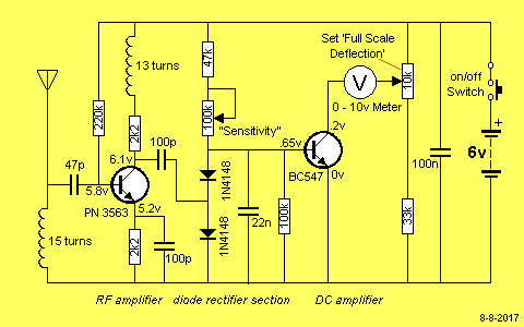
This is the circuit diagram:
FieldStrengthMeterMkICct.gif


I am struggling to understand the schematic regarding the 100K pot on the left marked "sensitivity".

As I understand it the wire coming from the base terminal of the BC547 transistor needs to be connected to terminal A of the pot, then the terminal B of the pot is to be connected to the 47K resistor. What about the wiper? I see with this pot the wiper is pointing back into the pot? Does this mean both terminal B and the wiper needs to be connected to the 47K resistor at the top?

Thank you for any help with this, I am stuck on this issue.
 
Yes, very strange.. Surely it'll work to some degree but I can't see the diodes doing anything that the B-E of the BC547 isn't doing first.. How is it usually done Dave?
 

(*steve*)

¡sǝpodᴉʇuɐ ǝɥʇ ɹɐǝɥd
Moderator
Yeah, it confused me. I thought that maybe the "sensitivity" control affects the bias of the transistor, with the greatest sensitivity when it is closer to cutoff as it will then be operating class B and only amplifying positive going half cycles.

I'm pretty sure those diodes look really nice, and that's about all.

I'm not sure my explanation is right.

This is either a piece of sublime design, or it has been put together without much thought and played about with until it kinda works. Either way, it's got me stumped.
 

davenn

Moderator
Yes, very strange.. Surely it'll work to some degree but I can't see the diodes doing anything that the B-E of the BC547 isn't doing first.. How is it usually done Dave?

definately weird, it would indicate that any rectified RF signal is going to get shunted to GND rather than being directed to the base of the BC547.
I would have expected at least one diode in series between the 100pF cap and the BC547 base.
I have used back to back parallel diodes often across the front end of a receiver cct to GND for protection against higher Rf voltages ie. the diodes will conduct when the voltage hits that 0.6 - 0.7 V region thus protecting the MOSFET/GaAsFET etc.

any way here'sa very simple and guaranteed to work FSM :)

cheers
Dave
 

Attachments

  • Field Strength Meter.gif
    Field Strength Meter.gif
    3.8 KB · Views: 5,182

(*steve*)

¡sǝpodᴉʇuɐ ǝɥʇ ɹɐǝɥd
Moderator
That circuit uses a 250uA meter. If you have a 200uA current range, that would be ideal.

If it goes over 200uA, switch to the next range up :)
 
The resistor values, voltage values, & general solutions all seem very fishy to me. Here's a rough remake of that circuit that might work better.
Now, I have neither calculated, checked or tested anything so I can't vouch for how well it'll work or what further adjustments have to be made.
I don't know where you got the original diagram from (it seems experimental to me) but it's better yet to go with a proven design, like Dave's.
 

Attachments

  • FieldStrengthMeterMkIICct.GIF
    FieldStrengthMeterMkIICct.GIF
    6.3 KB · Views: 816
any way here'sa very simple and guaranteed to work FSM :)

Dave,

I think your circuit is the better option to build - I have a question about L1 though - is this an air-wound coil or a choke - and if it is a choke, can I get anything in the 0.15-0.25 uH region?
 
Amusing that their schematic shows a 6V battery, but their built up unit is powered by a 12V battery.

Hehe, no wonder, their website is full of bugs.. Pun intended.. ;)

Their diagram has a small error compared to the PCB. Here's their "correct" diagram.
Their circuit works "in reverse" btw., as the meter dips lower as the signal increases..
Now it makes a little more sense; there's a voltage doubler drawing the bias current away from the base.. :)
 

Attachments

  • FieldStrengthMeterMkICct.gif
    FieldStrengthMeterMkICct.gif
    6.7 KB · Views: 273
Last edited:
Their diagram has a small error compared to the PCB. Here's their "correct" diagram.
Their circuit works "in reverse" btw., as the meter dips lower as the signal increases..
Now it makes a little more sense; there's a voltage doubler drawing the bias current away from the base.. :)

Thanks Resqueline,

The change I see you made is running the 100p cap to in-between the two diodes?

I came across this website while looking for crystal-locked FM transmitters. They had a field strength meter that used a series of LED's to indicate signal strength as well.
 
Top