Create an interface controlled by an MPU6050 sensor and Arduino through the Wekinator open source software platform.
This article will teach how to control a simple interface made in Processing through the movement of an MPU6050 sensor using the Wekinator software platform.
We'll start the project by interfacing the MPU6050 sensor with the Arduino UNO and sending the sensor output data to Processing.
In Processing, we'll calculate the YPR (yaw, pitch, roll) values and draw a 3D model that reflects the sensor's motions.
Next, we send the YPR values to the Wekinator.
After training, it will send the output data to the interface, which is controlled using the Dynamic Time Warping (DTW) algorithm.
To learn more about using Dynamic Time Warping in projects, check out our article, How to Program Dynamic Time Warping with Machine Learning.
Input Instructions
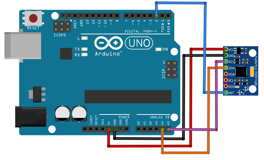
For the input aspect of this project, we'll need to connect the MPU6050 sensor with the Arduino UNO.
Reference the figure below for help on how to connect the sensor to the Arduino.
Figure detailing the connections between the MPU6050 sensor and Arduino UNO.
Installing the Arduino Libraries
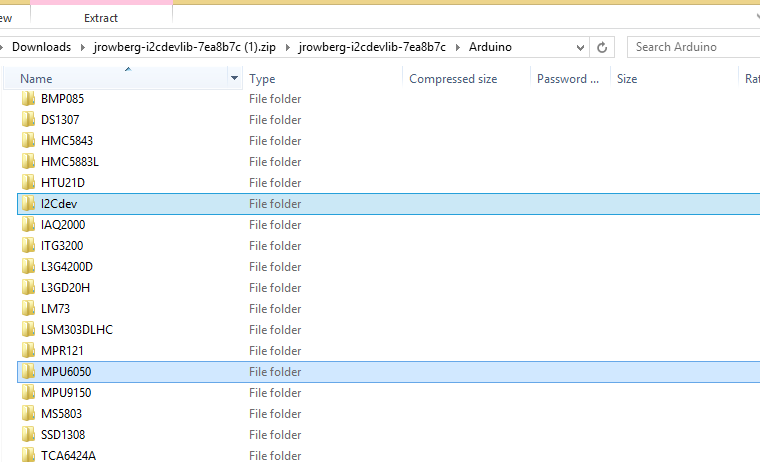
First, download the I2C and MPU6050 library from GitHub in order to interface with the Arduino.
After unzipping or extracting the download file, navigate to the Arduino folder, copy the I2C and MPU6050 folders and place them in the Arduino IDE library folder.
The location of the I2C and MPU6050 folders in the Arduino IDE library folder.
Uploading Code Process
Sub-title here
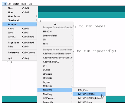
- Launch the Arduino IDE.
- Find the examples file under the MPU6050 folder.
- Open the MPU6050_DMP6 file.
Location of the MPU6050_DMP6 file under examples and the MPU6050 folder.
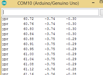
Now, upload the Arduino IDE code and the serial monitor will come up.
If it displays the output then that's an indication you've successfully interfaced the sensor with the Arduino.
The output data displaying in the Arduino.
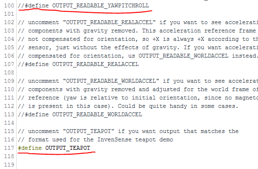
To send the data to Processing, some changes need to be made to the code.
First uncomment the 117 code line and comment the 100 code line.
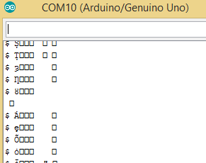
Upload the code again and it should show as unreadable characters in the serial monitor.
Processing Code Instructions
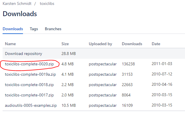
In order to receive data from the Arduino and move the 3D model, the 'toxiclibs' library will need to be downloaded from bitbucket.org.
Copy all folders within the zip file and paste them into the Processing library folder.
The Processing library folder can be found under: Processing Folder > Modes > Java > Libraries.
Now, paste the code below into Processing then upload.
The code is a modified version of the example included in the MPU6050 library.
import processing.serial.*;
import processing.opengl.*;
import toxi.geom.*;
import toxi.processing.*;
import oscP5.*;
import netP5.*;

OscP5 oscP5;
NetAddress dest;

ToxiclibsSupport gfx;

Serial port;                         // The serial port
char[] teapotPacket = new char[14];  // InvenSense Teapot packet
int serialCount = 0;                 // current packet byte position
int synced = 0;
int interval = 0;

float[] q = new float[4];
Quaternion quat = new Quaternion(1, 0, 0, 0);

float[] gravity = new float[3];
float[] euler = new float[3];
float[] ypr = new float[3];

void setup() {
    // 300px square viewport using OpenGL rendering
    size(300, 300, OPENGL);
    gfx = new ToxiclibsSupport(this);

    // setup lights and antialiasing
    lights();
    smooth();

    // display serial port list for debugging/clarity
    println(Serial.list());

    // get the first available port (use EITHER this OR the specific port code below)
    String portName = Serial.list()[0];

    // get a specific serial port (use EITHER this OR the first-available code above)
    //String portName = "COM4";

    // open the serial port
    port = new Serial(this, portName, 115200);

    // send single character to trigger DMP init/start
    // (expected by MPU6050_DMP6 example Arduino sketch)
    port.write('r');

    /* start oscP5, sending messages at port 9000 */
    oscP5 = new OscP5(this,9000);
    dest = new NetAddress("127.0.0.1",6448);
}

void draw() {
    if (millis() - interval > 1000) {
        // resend single character to trigger DMP init/start
        // in case the MPU is halted/reset while applet is running
        port.write('r');
        interval = millis();
    }

    // black background
    background(0);

    // translate everything to the middle of the viewport
    pushMatrix();
    translate(width / 2, height / 2);

    // 3-step rotation from yaw/pitch/roll angles (gimbal lock!)
    // ...and other weirdness I haven't figured out yet
    //rotateY(-ypr[0]);
    //rotateZ(-ypr[1]);
    //rotateX(-ypr[2]);

    // toxiclibs direct angle/axis rotation from quaternion (NO gimbal lock!)
    // (axis order [1, 3, 2] and inversion [-1, +1, +1] is a consequence of
    // different coordinate system orientation assumptions between Processing
    // and InvenSense DMP)
    float[] axis = quat.toAxisAngle();
    rotate(axis[0], -axis[1], axis[3], axis[2]);

    // draw main body in red
    fill(255, 0, 0, 200);
    box(10, 10, 200);

    // draw front-facing tip in blue
    fill(0, 0, 255, 200);
    pushMatrix();
    translate(0, 0, -120);
    rotateX(PI/2);
    drawCylinder(0, 20, 20, 8);
    popMatrix();

    // draw wings and tail fin in green
    fill(0, 255, 0, 200);
    beginShape(TRIANGLES);
    vertex(-100,  2, 30); vertex(0,  2, -80); vertex(100,  2, 30);  // wing top layer
    vertex(-100, -2, 30); vertex(0, -2, -80); vertex(100, -2, 30);  // wing bottom layer
    vertex(-2, 0, 98); vertex(-2, -30, 98); vertex(-2, 0, 70);  // tail left layer
    vertex( 2, 0, 98); vertex( 2, -30, 98); vertex( 2, 0, 70);  // tail right layer
    endShape();
    beginShape(QUADS);
    vertex(-100, 2, 30); vertex(-100, -2, 30); vertex(  0, -2, -80); vertex(  0, 2, -80);
    vertex( 100, 2, 30); vertex( 100, -2, 30); vertex(  0, -2, -80); vertex(  0, 2, -80);
    vertex(-100, 2, 30); vertex(-100, -2, 30); vertex(100, -2,  30); vertex(100, 2,  30);
    vertex(-2,   0, 98); vertex(2,   0, 98); vertex(2, -30, 98); vertex(-2, -30, 98);
    vertex(-2,   0, 98); vertex(2,   0, 98); vertex(2,   0, 70); vertex(-2,   0, 70);
    vertex(-2, -30, 98); vertex(2, -30, 98); vertex(2,   0, 70); vertex(-2,   0, 70);
    endShape();

    popMatrix();

    //Send the OSC message
    sendOsc();
}

void serialEvent(Serial port) {
    interval = millis();
    while (port.available() > 0) {
        int ch = port.read();

        if (synced == 0 && ch != '$') return;   // initial synchronization - also used to resync/realign if needed
        synced = 1;
        print ((char)ch);

        if ((serialCount == 1 && ch != 2)
            || (serialCount == 12 && ch != '\r')
            || (serialCount == 13 && ch != '\n'))  {
            serialCount = 0;
            synced = 0;
            return;
        }

        if (serialCount > 0 || ch == '$') {
            teapotPacket[serialCount++] = (char)ch;
            if (serialCount == 14) {
                serialCount = 0; // restart packet byte position

                // get quaternion from data packet
                q[0] = ((teapotPacket[2] << 8) | teapotPacket[3]) / 16384.0f;
                q[1] = ((teapotPacket[4] << 8) | teapotPacket[5]) / 16384.0f;
                q[2] = ((teapotPacket[6] << 8) | teapotPacket[7]) / 16384.0f;
                q[3] = ((teapotPacket[8] << 8) | teapotPacket[9]) / 16384.0f;
                for (int i = 0; i < 4; i++) if (q[i] >= 2) q[i] = -4 + q[i];

                // set our toxilibs quaternion to new data
                quat.set(q[0], q[1], q[2], q[3]);


                // below calculations unnecessary for orientation only using toxilibs

                // calculate gravity vector
                gravity[0] = 2 * (q[1]*q[3] - q[0]*q[2]);
                gravity[1] = 2 * (q[0]*q[1] + q[2]*q[3]);
                gravity[2] = q[0]*q[0] - q[1]*q[1] - q[2]*q[2] + q[3]*q[3];

                // calculate Euler angles
                euler[0] = atan2(2*q[1]*q[2] - 2*q[0]*q[3], 2*q[0]*q[0] + 2*q[1]*q[1] - 1);
                euler[1] = -asin(2*q[1]*q[3] + 2*q[0]*q[2]);
                euler[2] = atan2(2*q[2]*q[3] - 2*q[0]*q[1], 2*q[0]*q[0] + 2*q[3]*q[3] - 1);

                // calculate yaw/pitch/roll angles
                ypr[0] = atan2(2*q[1]*q[2] - 2*q[0]*q[3], 2*q[0]*q[0] + 2*q[1]*q[1] - 1);
                ypr[1] = atan(gravity[0] / sqrt(gravity[1]*gravity[1] + gravity[2]*gravity[2]));
                ypr[2] = atan(gravity[1] / sqrt(gravity[0]*gravity[0] + gravity[2]*gravity[2]));

                // output various components for debugging
                //println("q:\t" + round(q[0]*100.0f)/100.0f + "\t" + round(q[1]*100.0f)/100.0f + "\t" + round(q[2]*100.0f)/100.0f + "\t" + round(q[3]*100.0f)/100.0f);
                //println("euler:\t" + euler[0]*180.0f/PI + "\t" + euler[1]*180.0f/PI + "\t" + euler[2]*180.0f/PI);
                println("ypr:\t" + ypr[0]*180.0f/PI + "\t" + ypr[1]*180.0f/PI + "\t" + ypr[2]*180.0f/PI);

            }
        }
    }
}

void drawCylinder(float topRadius, float bottomRadius, float tall, int sides) {
    float angle = 0;
    float angleIncrement = TWO_PI / sides;
    beginShape(QUAD_STRIP);
    for (int i = 0; i < sides + 1; ++i) {
        vertex(topRadius*cos(angle), 0, topRadius*sin(angle));
        vertex(bottomRadius*cos(angle), tall, bottomRadius*sin(angle));
        angle += angleIncrement;
    }
    endShape();

    // If it is not a cone, draw the circular top cap
    if (topRadius != 0) {
        angle = 0;
        beginShape(TRIANGLE_FAN);

        // Center point
        vertex(0, 0, 0);
        for (int i = 0; i < sides + 1; i++) {
            vertex(topRadius * cos(angle), 0, topRadius * sin(angle));
            angle += angleIncrement;
        }
        endShape();
    }

    // If it is not a cone, draw the circular bottom cap
    if (bottomRadius != 0) {
        angle = 0;
        beginShape(TRIANGLE_FAN);

        // Center point
        vertex(0, tall, 0);
        for (int i = 0; i < sides + 1; i++) {
            vertex(bottomRadius * cos(angle), tall, bottomRadius * sin(angle));
            angle += angleIncrement;
        }
        endShape();
    }
}

void sendOsc() {
  OscMessage msg = new OscMessage("/wek/inputs");
  msg.add((float)ypr[2]); // x-axis
  msg.add((float)ypr[1]);  // y -axis
  oscP5.send(msg, dest);
}
After uploading the code, a window should come up like the one below.
Output Code Instructions
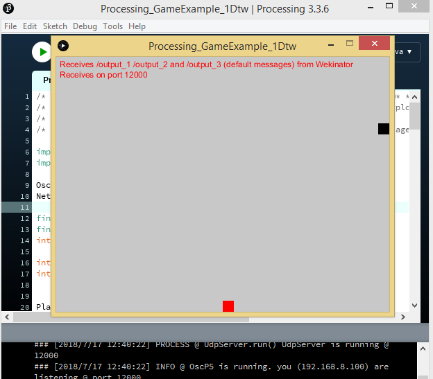
In terms of the output process, a simple interface will be set up to receive one DTW output from Wekinator.
Within the interface, a square box will move either left or right according to the Wekinator input it receives.
You can find and download the Processing sketch on the Wekinator website.
After downloading the 'Simple DTW-controlled-game' file and running it in Processing, it should look like the example below.
Wekinator Instructions
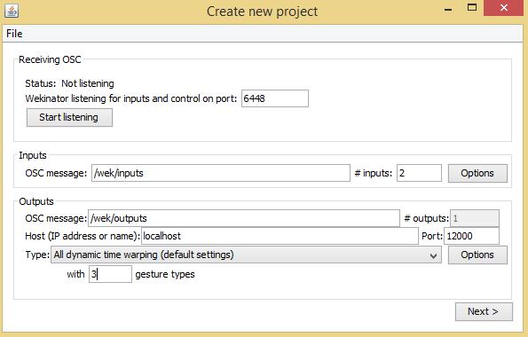
Launch the Wekinator software and follow these steps:
- Set the input values to 2.
- Set the output values to 1.
- Leave the output type to the default setting, 'all dynamic time warping' and designate 3 gesture types.
'Create new project' window displaying the input, output and gesture type fields in Wekinator.
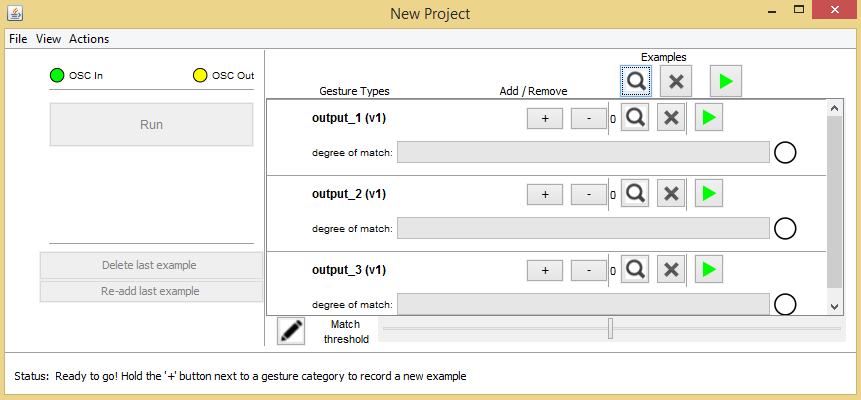
Click 'Next' and the 'New Project' window will pop up.
'New Project' window with output row fields in Wekinator.
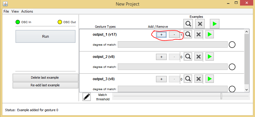
Then, click the 'Plus' button across the output 1 row and tilt the sensor left. The output will move the box in that direction.
'New Project' window with Add/Remove buttons circled.
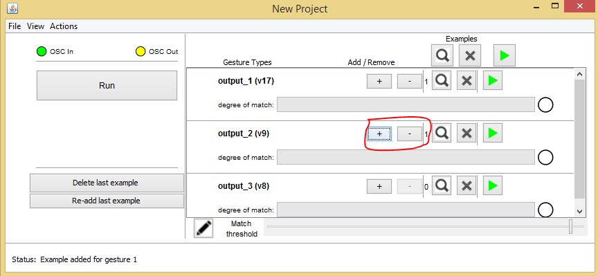
Now, click the 'Plus' button across the output 2 row and tilt the sensor right. The output will move the box accordingly.
'New Project' window with Add/Remove buttons in output 2 row circled in Wekinator.
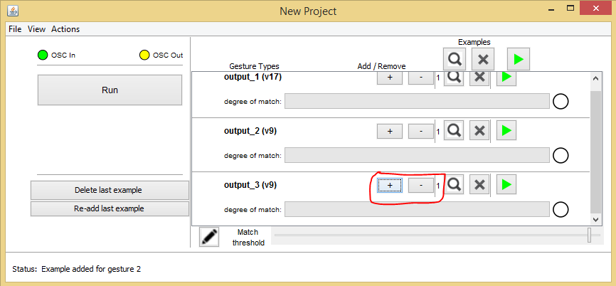
Lastly, click the plus button in the output 3 row and tilt the sensor backwards. The output will cause the box to jump.
'New Project' window with Add/Remove buttons circled in Wekinator.
'New Project' window with Add/Remove buttons in output 3 row circled.
After recording, train the Wekinator according to the samples and run the program.
The square box will then move in response to the direction the sensor is tilted.