In this project, we will design and learn a simple low-voltage DC short-circuit protection circuit.
A short circuit is a circuit or a portion of a circuit that is shorted. If the two ends of the load and power supply are connected by wires, it is called a short circuit. It occurs in both AC and DC circuits. If it is in AC, short circuit will affect the power supply of an entire area, but there are many levels of fuses and overload protection circuits from the power supply station to the house. If it is a DC source like a battery, a short circuit will overheat the battery and the battery will discharge faster. In some extreme cases the battery can even explode. There are multiple circuits to avoid short circuits, and there are also many fuses to protect against overload. (see what is fuse)
In this example, we will design and learn a simple low-voltage DC short-circuit protection circuit. The purpose of this circuit is to make the micro-control circuit run more safely and protect it from the influence of other parts of the circuit.
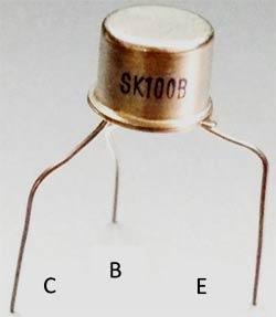
SK100B PNP Transistor
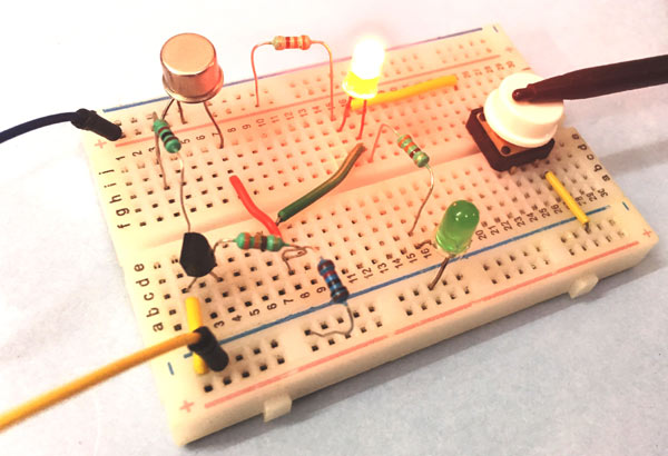
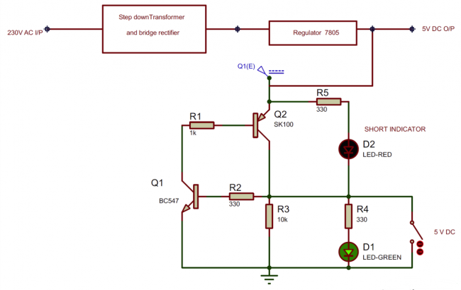
Short circuit protection circuit
The most common short circuit is that the positive and negative pins of the battery are connected by a low-resistance conductor, such as a wire. In this case, the battery may catch fire or even explode. Many cell phone battery fires often happen this way.
To avoid short circuit, we need to add short circuit protection circuit. The short circuit protection circuit will shunt part of the current or cut off the connection between the circuit and the power supply.
Sometimes power outages or sparks occur when we use faulty appliances such as ovens and irons. This is because the current is too high somewhere in the circuit, which may cause leakage or fire. To avoid such losses, we often use fuses or circuit breakers. In the event of a short circuit, the fuse or circuit breaker will cut off the house power. Fuse circuit breaker circuit is also a kind of short circuit protection circuit, in which the low-resistance wire will fuse under high current, thereby cutting off power supply.
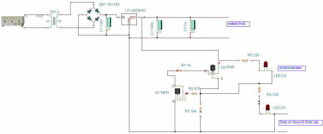
Circuit diagram
How the short circuit protection circuit works
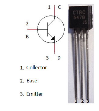
The above short-circuit protection circuit consists of two transistor circuits, one is the circuit of the BC547 NPN transistor, and the other is the circuit of the SK100B PNP transistor. The power input is a 5V DC power supply, which can be implemented with either a battery or a transformer.
The working principle of the circuit is very simple. When the green LED D1 is on, it means that the circuit works normally and there is no risk of damage. When the red LED D2 lights up, it means that a short circuit has occurred.
When the power is turned on, the transistor Q1 is biased on and the LED D1 lights up. There is no short circuit during this time, so the red LED D2 is turned off.
The lighting of the green LED D1 also means that the power supply voltage is almost equal to the output voltage.
In the simulation circuit, we use a switch on the output to create a "short circuit". When a short circuit occurs, the output voltage drops to 0V and the Q1 base voltage is 0V so it is no longer on. The collector voltage of the transistor Q2 also drops to 0V and no longer conducts.
So now the current starts to travel along the short-circuit path (through the switch) and flows through the red LED D2 to ground. At the same time, D2 starts to conduct because of forward bias, the LED lights up to indicate a short circuit, and the current is diverted to D2 instead of damaging the entire circuit.