This article shows how to create a ROS package for a simple 4-DOF robot arm and simulate a predefined joint path in Rviz
Robots are usually expensive and quite susceptible to damage and undesired interaction with themselves or their surroundings. Three-dimensional simulation is a sustainable method to test and rapidly iterate during robot application development. Robot Operating System (ROS) is a middleware for multiple robot software tools and also provides simulation platforms like Rviz and Gazebo.
This article shows how to create a ROS package for a simple 4-DOF robot arm and simulate a predefined joint path in Rviz. The code repository can be found on GitHub.
What is a Robotic Arm?
Robotic arms are the most common robots to exist in the last century. They are built out of multiple actuators and passive links forming an actuated chain that can be used to manipulate objects using different end-effectors. They are extremely useful in industry as well as personal settings for assembly, drilling, machining, pick-and-place, and other applications. A robot arm could have revolute or prismatic joints for rotation or linear motion respectively.
Designing the Robotic Arm
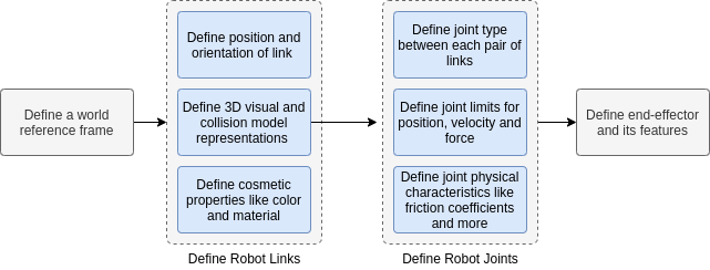
In this article, we design a simple robot arm with four revolute joints and one prismatic joint. A Universal Robot Description Format (URDF) file with the robot’s kinematic, visual, and collision model representation is needed for the robot’s interaction with ROS. The inertial model may also be required for applications dealing with the robot dynamics.
Steps to define a robotic arm URDF file (Image Source - Original)
The URDF file is an XML file with dedicated tags for physical features like the material and color of the links. For the 3D visual representation of the robot links, the <visual></visual> tags are used. They carry information about the geometry (within <geometry></geometry> tags) which can be a primitive shape usually centered at its geometric center or a mesh with the center defined in the 3D modeling software itself.
URDFs support visual representation using primitive shapes or 3D meshes like COLLADA and STL files. The collision model is similar to the visual model within <collision></collision> tags but ideally with a coarser representation of the 3D model. The inertial model of the link is defined within <inertial> </inertial> tags and has information about the mass and the inertia matrix.
The joints are defined within the <joint></joint> with information about the origin, axis of rotation, parent and child links, and limits for positions, velocities, accelerations, and forces. They often have friction and damping coefficient values as well.
The URDF file provided in the package, robot_arm.urdf, is formed of primitive boxes (cuboids) and cylinders. It does not have any end-effector attached. After the robot description is ready, follow the steps to create a ROS package to simulate the design.
Simulation Pipeline
ROS is highly modular in nature, allowing the use of multiple tools and services for each individual aspect of robotics. For this simulation task, execute the following steps on Ubuntu 16.04 environment with ROS Kinetic.
Steps involved in the simulation task (Image Source - Original)
akshay@akshay:~$ mkdir -p catkin_ws/src
akshay@akshay:~$ cd catkin_ws
akshay@akshay:catkin_ws$ catkin_make
akshay@akshay:~$ source devel/setup.bash
- Download and extract the provided ROS simulation package (robot_arm_simulator) inside the catkin_ws/src folder:
akshay@akshay:~$ cd catkin_ws/src
// Download and extract the folder or clone the github repository here
akshay@akshay:catkin_ws/src$ cd ../
akshay@akshay:catkin_ws$ catkin_make
akshay@akshay:catkin_ws$ source devel/setup.bash
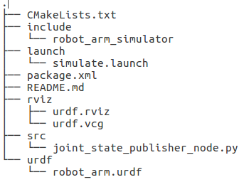
- The robot_arm_simulator package has this file structure.
ROS Package File Structure (Image Source - Original)
- launch - Contains all the launch files
- src - Contains the node that publishes the joint instructions
- urdf - Contains the URDF model of the robot
- rviz - Contains the default configurations for the Rvix simulator
Understanding the Launch File
The launch file simulate.launch is responsible for launching the roscore master service and the other necessary nodes for visualization in Rviz.
<launch>
	<arg name="model" default="$(find robot_arm_simulator)/urdf/robot_arm.urdf"/>

	<arg name="rvizconfig" default="$(find robot_arm_simulator)/rviz/urdf.rviz" />

	<param name="robot_description" command="$(find xacro)/xacro --inorder $(arg model)" />

	<node name="joint_state_publisher" pkg="joint_state_publisher" type="joint_state_publisher">
		<rosparam param="source_list">["joint_states_interpolated"]</rosparam>
	</node>
	<node name="robot_state_publisher" pkg="robot_state_publisher" type="state_publisher" />
	<node name="rviz" pkg="rviz" type="rviz" args="-d $(arg rvizconfig)" required="true" />
</launch>
- This launch file sets the URDF model inside the package as the robot_description parameter for Rviz to visualize.
- It sets the provided Rviz configuration file as the rvizconfig parameter.
- It starts the joint_state_publisher node which listens for sensor_msgs/JointState messages on the joint_states_interpolated topic. This node publishes the received joint positions for the robot on the joint_states topic. The joint_states_interpolated topic is populated by the custom node defined in src/joint_state_publisher_node.py.
- It also starts the robot_state_publisher node which uses the robot_description (set above) and listens to the joint_states topic for the robot. This node is responsible for creating the kinematic chain for the robot using the joint positions and forward kinematics.
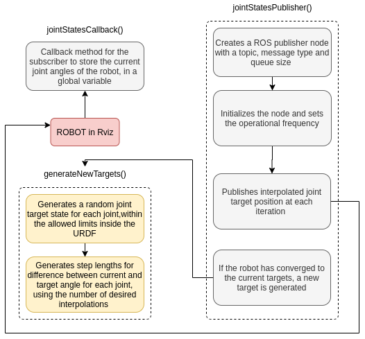
Understanding the Custom Node
The src/joint_state_publisher_node.py node has a ROS subscriber listening to the robot’s current joint positions. It creates a random joint target for the robot and then publishes the interpolated joint target position for each iteration of the ROS execution cycle. The completed execution is explained in the diagram below.
Node Operation (Image Source - Original)
Running the Robotic Arm Simulation
To run the simulation, follow these steps:
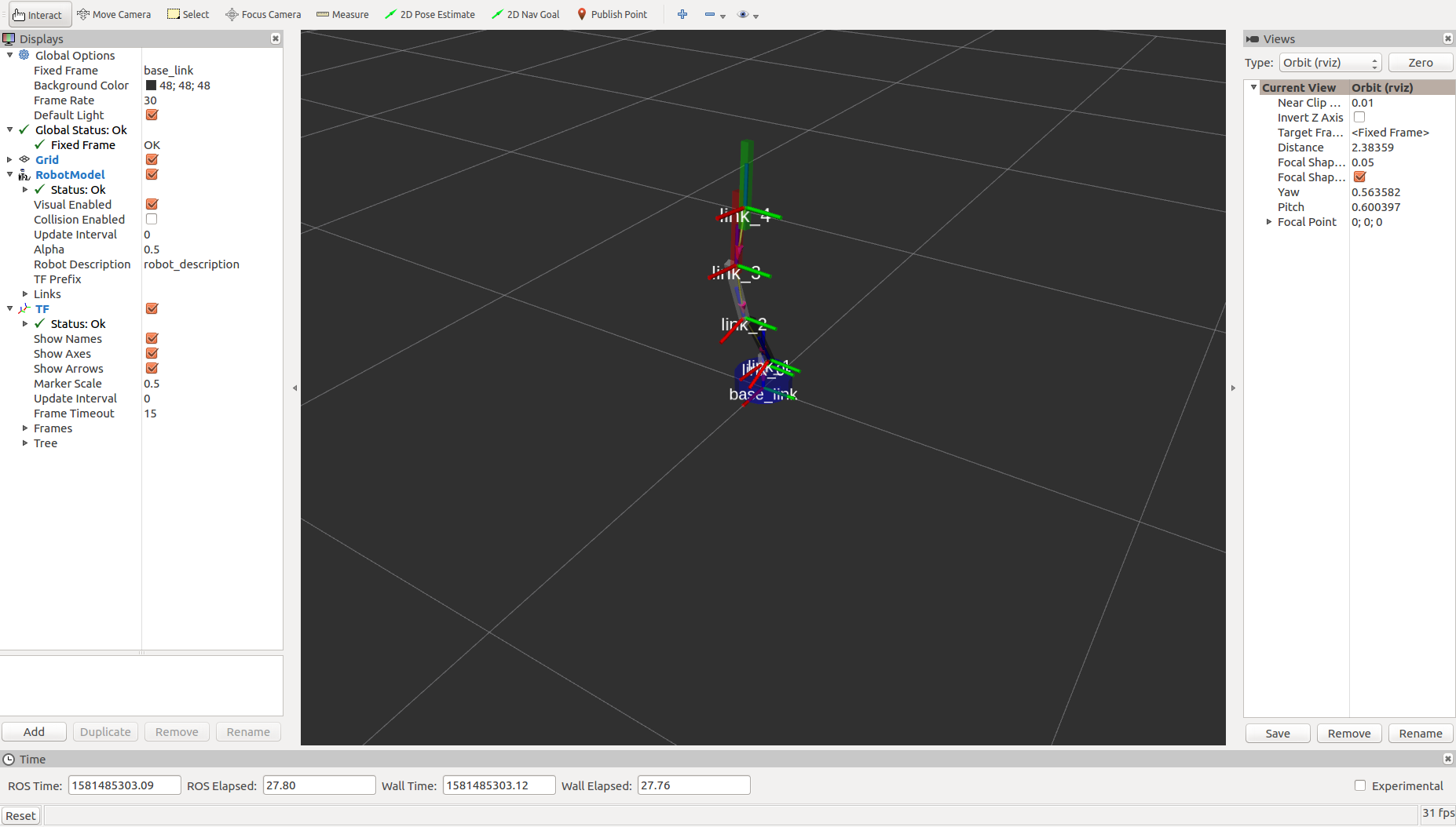
- In the terminal, run roslaunch robot_arm_simulator simulate.launch This opens up the Rviz simulator and the robot model is visible but it can’t move yet.
- In another terminal, run rosrun robot_arm_simulator joint_state_publisher_node.py.
This runs the custom ROS node explained above and the robot starts executing the random targets it is commanded to.
Rviz with robot model, TF frames and joints (Image Source - Original)
Results and Conclusions
ROS is a fairly simple tool to get started with robot software development. The ROS package provided here is easily used for simulation of a virtual robot. The package can be tried with different more meaningful target positions for the robot joints, different interpolations, different operational frequency, and different kinematics features.
The next part of the article series covers extending the package to publish the same target commands to an actual robot for real-time simulation and visualization.