Learn how you can use an affordable LiDAR sensor in your robotics design and how to set it up in ROS.
Robots use a plethora of sensors for proprioception (sensing the robot’s own state) and exteroception (sensing the surrounding environment).
Common proprioceptive sensors include the inertial measurement unit (IMU), encoder, and GPS. The rich information available in the environment is obtained using sensors like a camera, LiDAR, and RADAR. This article discusses LiDAR technology, including use and applications in robotics — specifically using ROS.
What is LiDAR?
Light detection and ranging (LiDAR) is a remote sensing technology. It usually has a source of laser (a source of optically amplified light) pulse and a receiver that accepts the reflection. It uses different computational techniques to find the distance between the source and the target. The output is usually a point cloud carrying range/distance information and orientation of the corresponding line-of-sight.
How does LiDAR work?
The basic principles for traditional LiDAR have been seen in time-of-flight-based distance measurement and triangulation-based measurement.
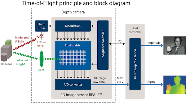
The ToF concept uses the delay time between the signal emission and its reflection to compute the distance to the target. The time delay is not measured for one particular beam’s round trip.
Basic overview of how ToF works. Image courtesy of Mark Hughes.
Instead, the phase shifts for multiple signals are used to indirectly obtain the ToF and then compute the distance. The triangulation method is used to measure the distance between the source and the obstruction.
LiDAR is a fairly expensive technology due to its high-precision and high-resolution performance. Compared to an ultrasonic or an infrared sensor that gives us a measure of distance along the line-of-sight, LiDAR is capable of providing 2D and 3D distance scans with very fine angular resolution. While traditional LiDAR is mechanical and has a motor-driven rotating sensor, the latest technology has introduced solid-state LiDAR which is more reliable and resistant to vibrations and has no moving parts.
Using a LiDAR Sensor With ROS
Traditionally, LiDAR sensors were very expensive — often to the tune of $10,000 and above — when they had limited applications in terrain mapping and security. Owing to the large market of LiDAR use in autonomous vehicle technology and robotics, there have been substantial hardware and software developments in the technology. Point cloud generated by LiDAR can easily be processed with the PCL library and also offers ROS support.
The YDLiDAR X4 Sensor
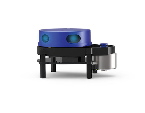
In this article, we are using the $99 YDLIDAR X4 sensor which is cheap and easy-to-use with a satisfactory performance for non-critical applications. The X4 is a triangulation-principle-based LiDAR with a rotating platform that carries a laser emitter and a receiver lens. It is a 360° 2D rangefinder with up to 5kHz frequency and 6Hz-12Hz motor speed. It also has a fine angular resolution of 0.48°-0.52° and a range of 0.12-10m.
The YDLIDAR X4 sensor. Image courtesy of YDLIDAR.
Like several other plug-and-play LiDARs, the X4 has a USB interface. It uses a serial communication interface to provide data to the machine. The YDLIDAR datasheet carries a detailed explanation of the features and specifications.
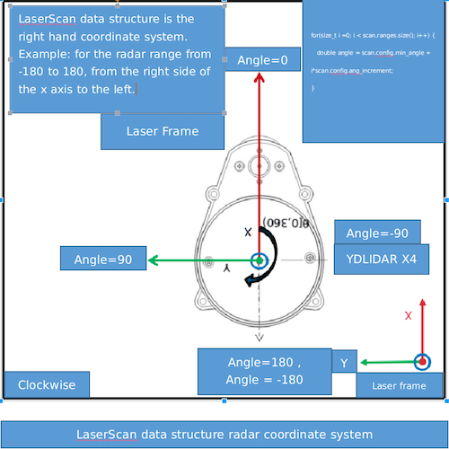
As the LiDAR provides data in the form of range and orientation, it is important to know the coordinate system. The default system is a polar coordinate frame with the zero angle along the motor axis, clockwise positive angle direction, and pole at the center of the rotating core. The ROS package uses the zero angle axis as the +X-axis.
Polar and Cartesian Coordinate Frames. Image courtesy of YDLIDAR GitHub.
Setting Up the X4 in ROS
The already available X4 ROS package allows us to configure the device, setup the serial communication hardware interface, and visualize the realtime point cloud data in Rviz.
Use the following steps.
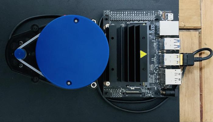
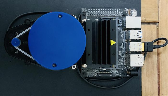
1. Connect the X4 sensor to the USB module using the provided headers. Then connect the board to a Jetson Nano with a USB to micro-USB cable.
2. As a prerequisite, the machine should have a Ubuntu 16.04 installed with ROS Kinetic and a catkin workspace names ~/catkin_ws.
3. Clone and add the YDLIDAR ROS package.
~$ cd catkin_ws/src
~$ git clone https://github.com/EAIBOT/ydlidar.git
~$  cd ../
~$ catkin_make
Now the package should be added to the ecosystem. Use the command rospack list | grep ydlidar to confirm the same.
4. The package already provides shell script to configure the serial communication protocol appropriately. Run this to automatically handle the /dev/tty<USB o ACM># serial port and create a /dev/ydlidar serial port for the YDLIDAR.
~$ roscd ydlidar/startup
// Make the shell script to an executable
~$ sudo chmod 777 ./*
~$ sudo sh initenv.sh
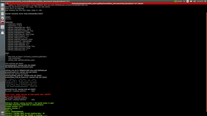
5. Run the launch file to visualize the data in Rviz. The motor starts spinning at the desired frequency and you can see the point cloud data in Rviz appearing after a while.
roslaunch ydlidar lidar_view.launch
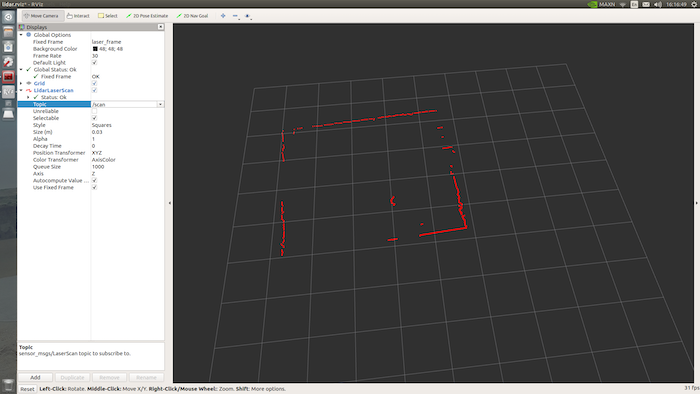
The terminal outputs the various configurable parameters’ minimum and maximum range and angle, baud rate, and more. You can configure these parameters in the package /ydlidar/launch/lidar.launch file. It publishes the data to the /scan topic and Rviz visualizes the same.
Point Cloud Visualization for my room.
This was a sample application for 2D LiDAR visualization but can be used in conjunction with ROS mapping tools like gmapping to create occupancy grids. Such maps are used in robot navigation and Simultaneous Localization and Mapping (SLAM) applications in robotics.
Using 3D LiDAR offers richer information about the environment and more accurate and finessed maps in realtime.
