Give your workshop space a boost with your own IoT-controlled frequency generator using RIOTOUS.
Test equipment is vital in any workshop environment, but such tools are normally not computer controlled. In this project, we will build a simple frequency generator that can be controlled via the internet using RIOTOUS.
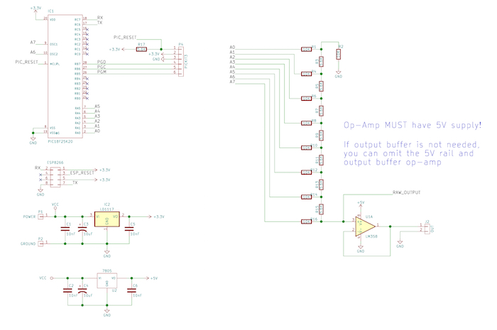
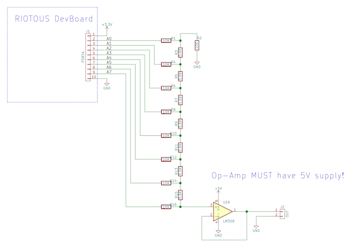
Schematic
RIOTOUS dev board schematic
How the IoT Frequency Generator Works: The Schematic
This project has three main components: the microcontroller that runs the RIOTOUS framework, the firmware itself, and the R2R DAC. Some PIC devices have digital-to-analog converters built into them, but the PIC16F516 does not. Therefore, to produce an analog signal with the PIC16F1516, we have two options: either use PWM and an RC circuit or use an R2R ladder circuit.
While the PWM circuit allows for a wide range of voltage outputs by adjusting the duty cycle of the PWM, the R2R is a personal favorite for multiple reasons. First, R2R ladders are incredibly simple and only composed of resistors. Second, they respond instantly, and so can be used at higher frequencies than their PWM counterparts.
The R2R ladder uses proportional weighting on the input resistors such that the highest bit produces a voltage output that is half of the maximum, while the lowest bit produces an output voltage that is equal to the smallest possible step.
In our case, we are using an 8-bit output, which gives us 255 steps, and since our circuit is a 3.3V system, bit 7 will produce a voltage of 1.5V while bit 0 will produce a voltage of 3.3/256 = 0.0129V. When all bits are on, all of the proportional output voltages add up to give 3.3V.
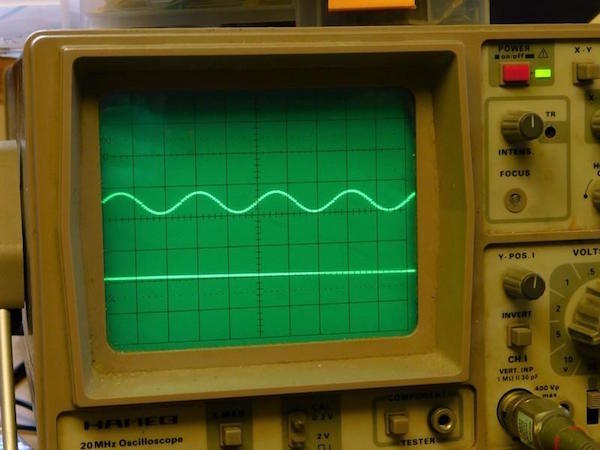
While this method can be used to produce analog signals, there is a serious downside; the output is quantized. The best way to understand what this means is to see the probed output:
Since there is a finite size to the smallest step value, steps produce sharp increases and decreases of voltage levels. This results in impure waveforms that may not behave exactly as their pure analog counterparts.
With the R2R ladder producing the stepped analog signal, the final step is to buffer it as to improve the output impedance. This project uses an LM358, but be warned about the LM358, as it cannot operate near the positive rail.
If the LM358 was powered by the 3.3V rail, the maximum voltage it can output would be VCC – 1.5V, and in our case that would correspond to approximately 1.8V. Therefore, half of the output waveform would be clipped and would not work, so to get around this, the LM358 uses an external power supply (5V works well) to increase its maximum operating voltage.
How the IoT Frequency Generator Works: The Firmware
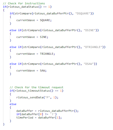
The firmware for the frequency is split into two main areas: the RIOTOUS framework and the frequency waveform generation. While RIOTOUS itself has complex aspects to it, using RIOTOUS is easy, and the code that handles commands from the controller program (i.e., the RIOTOUS server) is also simple.
When the circuit first starts up, it configures the controller to use the internal oscillator, correctly configure IO ports, and ensure that key variables are at known values. Then the microcontroller runs the RIOTOUS configuration, which correctly configures the UART modules, RIOTOUS engine, and other needed variables. With that done, the device then attempts to connect to the designated Wi-Fi network and server. Once those two actions have been completed, the microcontroller runs the main code bulk that handles the waveform generation.
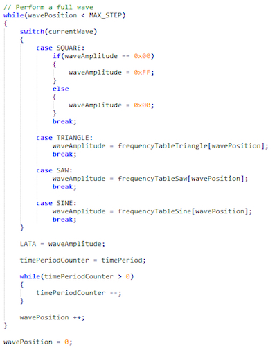
The waveform generation code itself is rather simple and mainly uses look-up tables to produce the digital outputs that get converted to analog signals.
The sine, triangle, and sawtooth waveforms use 32-byte arrays that contain absolute values of their respective waveforms at specific times.
The number of points could be increased and this would smooth out the waveforms (making them purer), but this comes at a cost of maximum frequency. Therefore, you as the final designer has to decide what is more important, purity or speed. Personally, speed is more important and thus I have opted for the use of 32 steps. One method of increasing the speed may be to use RAM arrays as opposed to ROM arrays (since table lookups on PICs can be slow).
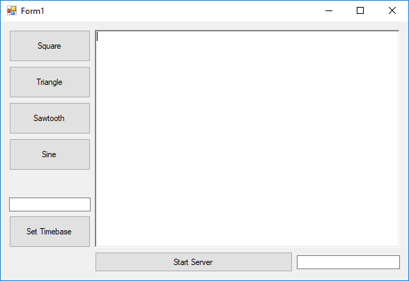
The Main Program/Server
The application that controls the frequency generator is written in VB.net and is also the RIOTOUS server that the frequency generator connects to. However, we could have easily just made the program using MMF2 and had the server separate, but lately, VB.net has been neglected, so I made the decision to use VB.net instead of MMF2.
Our VB.net application has just a few objects, including buttons to choose the waveform output, a single text box that we can enter our time base into (between 0 and 255), the server log window (useful for seeing activity), and a start server button.
When the server is started, the RIOTOUS framework in the background awaits incoming connections on the advertise port 333, and when a device connects, the server responds with the new port to connect to and then closes the connection.
You can control the frequency generator with one of five commands:
- “SQUARE” – Use the square waveform
- “TRIANGLE” – Use the triangular waveforms
- “SAW” – Use the sawtooth waveforms
- “SINE” – Use the sine waveforms
- Set the time base (as byte) by only sending a byte
Construction of the Frequency Generator
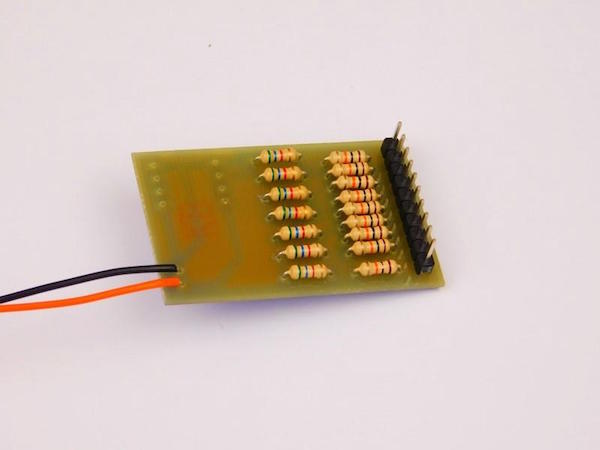
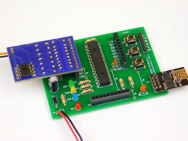
This project can be constructed using most circuit construction techniques, including breadboard, stripboard, matrix board, and PCB. For those who are new to electronics, using a soldered technique is not advised, as you can easily make mistakes. In this project, I used a RIOTOUS DevBoard for the sake of convenience, and it was easy to make an external R2R ladder that connected straight into the socket.
Thanks to a glitch in KiCad, I had to mount the LM358 in an odd way!
This project could easily be expanded to make a more customizable function generator with features including customizable waveforms, adjustable gains, and even triggering. Since the project is connected to a VB.net program via the internet, plenty of information can be transferred between the two, which effectively gives IO capabilities to powerful computing devices like laptops and desktop PCs.