Learn how to build a customizable IoT-controlled RC car with the RIOTOUS platform.
RIOTOUS is an IoT system that makes connecting low end microcontrollers to the internet easy. However, its use goes beyond data gathering and simple data transmitting, and in this project we will see how to use it to control a simple RC vehicle.
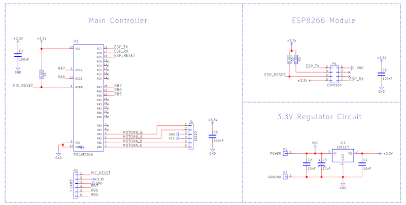
Schematic
How the Remote-Controlled Car Works
The RC Vehicle and Firmware
Like many RIOTOUS projects, the circuit is very simple, consisting of a 3.3V linear regulator circuit, an ESP-01 Wi-Fi module, and a PIC16F1516 microcontroller. The motors are controlled using the L9110S Dual Motor Controller, which at its core is essentially an H bridge circuit. This module has four inputs (two for each motor) and is connected to PORT A. While the circuit shown uses a single power source, it may be necessary to use two separate power supplies if the current draw from the motor causes brown-outs, which result in microcontroller resets.
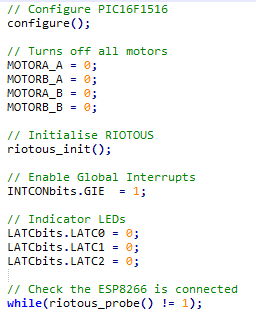
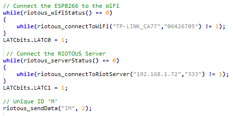
When the PIC first starts, it runs configuration code, which configures the ports, internal oscillator, and RIOTOUS. With the configuration done, the firmware then attempts to connect to a valid Wi-Fi network and then attempts to connect to our RIOTOUS control program (the server). Once a valid connection has been made, the PIC then informs the server of its unique ID so the server can easily send data to it.
The main loop code executes one of two tasks: move the motors depending on the incoming data from the server, or respond to a timeout check with a ping. Before we look into the motor control, we should look at the timeout check first, since this is a new feature in RIOTOUS V0.2.
A device that accepts a TCP socket (either an ESP8266 or VB.net program) does not know when a connection has just been terminated. Therefore, the VB.net server will ping all connected devices every so often to check if they are still connected. If a device responds, the connection must still be alive, but if the server receives no response within 10 seconds, it is assumed that the connection has been lost. RIOTOUS V0.1 does not implement this well, and the client device could crash (due to stack overflow) when a timeout check was sent by the server.
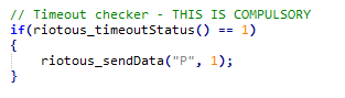
RIOTOUS V0.2 gets around this by moving the timeout check/ping to the main code loop. While this may not have been needed in mid-range microcontrollers, some low-end devices (such as the PIC16F1516), have a limited stack, and thus the ping response would result in a stack overflow. So every RIOTOUS project requires the following section of code in the main loop:
The RC vehicle can do one of four movements:
- Move forward – Executed upon receiving “DFORWARD”
- Move backward – Executed upon receiving “DBACKWARD”
- Turn clockwise – Executed upon receiving “DCLOCKWISE”
- Turn anti-clockwise – Executed upon receiving “DANTICLOCKWISE”
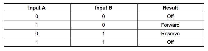
All of the commands start with the letter D, since the client RIOTOUS software does not remove the first letter from data transactions that identify the data type. The four functions involved with controlling the motors via the L9110S use identical code, except for the motor direction control. The L9110S module has four inputs for controlling two motors (two inputs A and B per motor).
- To move forward, both motors are configured into Forward
- To move backward, both motors are configured into Reverse
- To rotate clockwise, the right motor is reversed while the left motor is moved forward
- To rotate anti-clockwise, the right motor is moved forward while the left motor is reversed
The Server/Controller
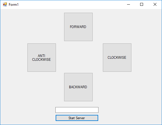
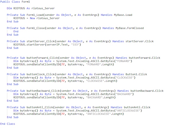
The server that the client connects to is also the controller that commands to the RC vehicle can be sent from. The form application, written in VB.net, consists of four buttons for direction control, a start server button, and a textbox for the server IP. To use the program, the textbox needs to have the local IP address (for example, my server has a local IP address of 192.168.1.200) before the server start button is pressed, otherwise the RIOTOUS server class won’t be able to initiate the server.
Once the server has been started, pressing one of the four buttons will send the corresponding command to the client to move the RC vehicle in that direction. Note that the data sent from the server does not need to include the letter D at the beginning.
Construction
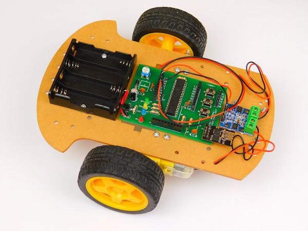
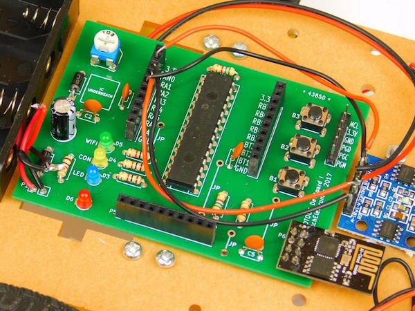
Building this project requires multiple tools and can be done using different methods. The main controller could be customized on a breadboard, stripboard, matrix board, or PCB. However, for convenience, this project has taken advantage of a RIOTOUS devboard that has external IO connectors.
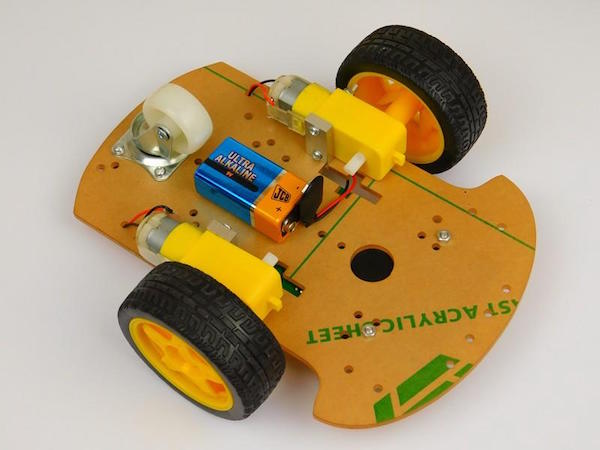
The RIOTOUS-controlled car
Depending on your power supply, a second separate power supply will be needed for the motor controller. If the motors draw too much current too fast, the voltage on the VCC line can drop enough to cause a brown-out, which results in a PIC reset. Ways around this include the use of inductors, capacitors, and dedicated power control circuitry, but for the sake of simplicity, it is easier to use two supplies.
A second power supply underneath for powering the motors separately.
The main RIOTOUS dev board.