This alarm clock has no reset button or display, but instead requires the user to play a game to disable the alarm.
Alarm clocks are useful for waking you up, but when it comes to actually getting you out of bed, not so much. In this project, we will build a RIOTOUS IoT alarm clock that has no reset button or display, but instead requires the user to play a game on the RIOTOUS server to disable the loud alarm.
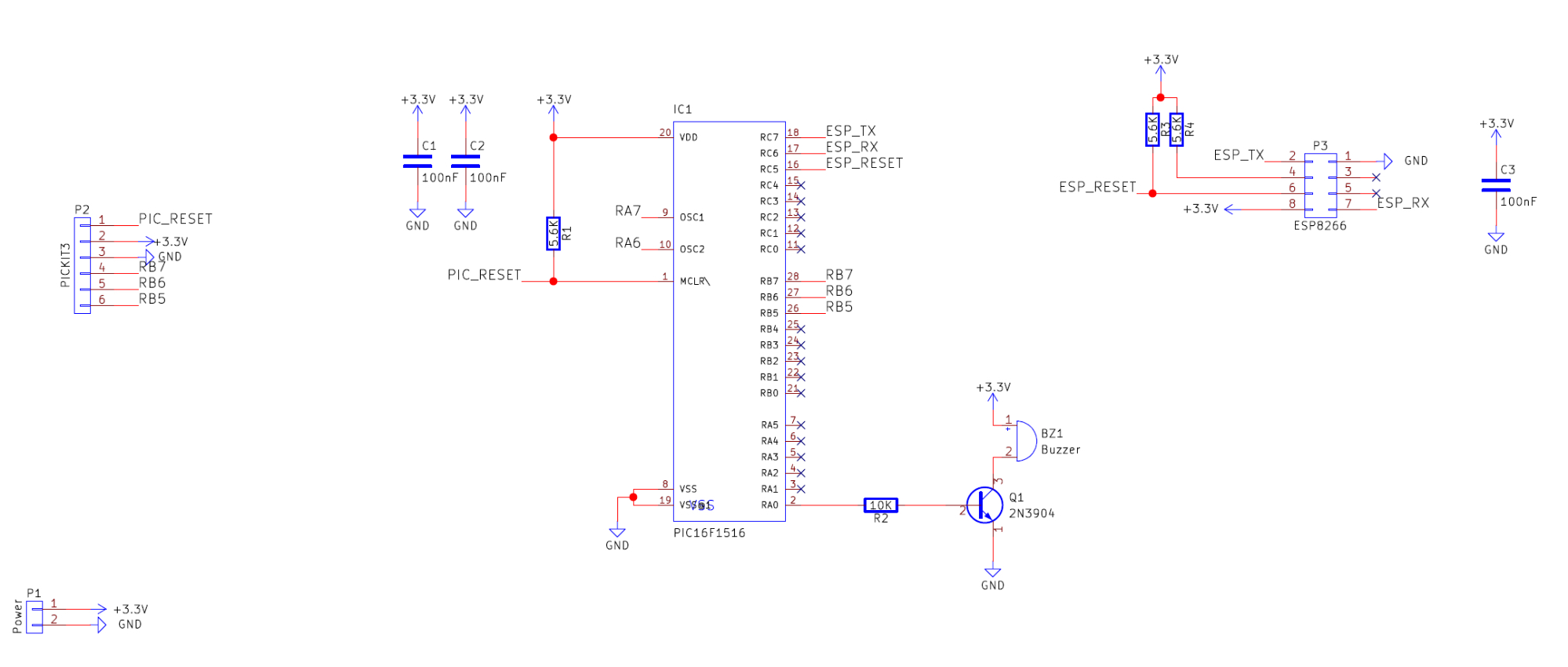
Schematic
How the Alarm Clock Works
Getting out of bed (even with a loud alarm clock) is incredibly difficult for some of us. Even if you place your alarm clock on the other side of the room, it is still easy to jump back into bed! However, if you are out of bed for more than a minute, your chances of staying up may be better. So the objective of this project is to not only get you out of bed, but to also challenge your brain to keep you awake!
The project consists of three main parts:
- The RIOTOUS beeper circuit
- A RIOTOUS server
- MMF2 RIOTOUS game
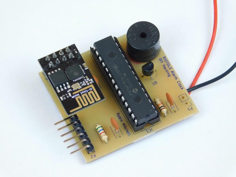
The circuit is very simple, consisting only of an ESP8266 module, a PIC16F1516, a beeper, and some external circuitry. When the PIC first turns on, it executes configuration code as well initiating the RIOTOUS engine that handles all of the IoT communication with the server. Once configured, the PIC continually awaits one of two commands from the server: turn the alarm on or turn the alarm off (these commands are found in the arrays buzzON and buzzOFF). You may notice that the commands both start with the letter D; this is because when data is sent using RIOTOUS, the first byte is used to indicate the data type that is being sent. D stands for DATA (which is what we will receive), R stands for redirect (used to enable two RIOTOUS devices to communicate through a server), and I stands for ID assign. In our project, our alarm buzzer has the unique ID “A” and the reason we use a letter instead of a number is that it is easier to deal with in MMF2.
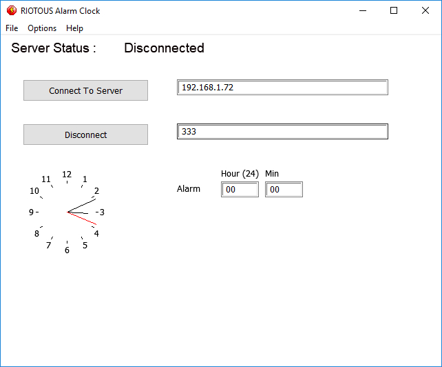
The RIOTOUS server itself is only a vanilla RIOTOUS server with a log window and a start server button. The server has no other functionality because it will merely relay messages from the MMF2 game to the RIOTOUS alarm. So for this project, we can reuse the RIOTOUS server used in our previous RIOTOUS project, the wireless game controller.
The MMF2 RIOTOUS game is where most of the magic happens in this project. This application is split into two frames with the first frame running the alarm code while the second frame contains the brain game that requires quick thinking. The alarm frame recycles a lot of code from the RIOTOUS pong game but a few changes have been made. One of the issues with MMF2 is that while it is a great piece of software not everyone likes to pay for such software. Therefore, this MMF2 project has been made configurable with the use of edit boxes so anyone should be able to use it on their computer (by running the exe file) and not need MMF2 to run. However, if you wish to makes changes to the program then you will need MMF2.
So once correctly configured and a successful connection has been made to the server, the program constantly compares the hours and minutes to the hours and minutes entered in the edit boxes to the right of the clock. When the hours and minutes match, the application creates a sub-application whose frame is set to frame 2 (the question/answer frame). At the same time, the buzzer on the alarm is turned on, which results in an ear-piercing noise that is guaranteed to get most people out of bed. When the pop-up window is closed, the main application informs the alarm to turn off, but the pop-up window cannot be closed by clicking the cross, as this has been disabled. Instead, the alarm can only be turned off by getting 10 questions correct.
The question/answer system is simple yet effective; they are simple addition problems, but you only have 5 seconds to solve them. First, two random numbers are generated between 0 and 99, and a third random number is generated between 1 and 4. The two numbers are added together, resulting in an answer, while the third random number selects one of the buttons to be the correct answer. The other buttons are assigned random numbers between 0 and 200, and only by clicking the correct button will the score be incremented. Despite being limited, this system creates a very challenging quiz because of the short amount of time allowed to select the right answer. If the wrong answer is pressed, a new question is generated, so randomly pressing buttons is not any faster than trying to determine the correct answer. Once the score has reached 10, the frame closes itself, and this closing is detected by the main application, which tells the alarm to turn itself off.
Construction
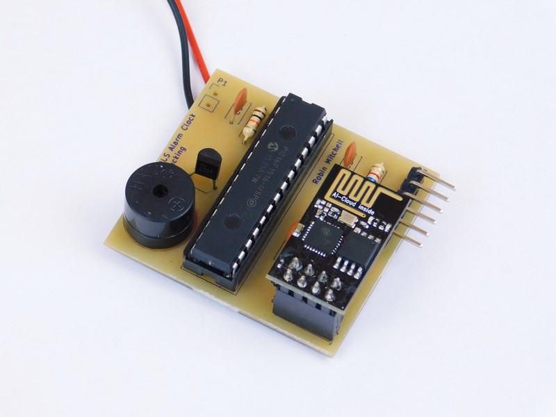
This project is very easy to construct and can be done using multiple methods. Such methods include stripboard, breadboard, matrix board, and even a PCB. This project uses a PCB to demonstrate the size of the alarm when on a custom board. However, if a custom circuit is not wanted, then a RIOTOUS devboard could be used (see MitchElectronics).
While not discussed in this tutorial, you will need to provide an external 3.3V source as well as designing a system that prevents someone from disconnecting the alarm in a fury. One idea would be to scrap the metal case of an ATX power supply, mounting the circuit internally, and then providing power via a fixed mains wire (with all proper safety devices and power management). That way, unless you have tools on hand, you will be kept awake until 10 questions have been answered!
Downloadable Files
Related Articles