Learn how you can use Python's standard GUI, Tkinter, to control the GPIO pins on your Raspberry Pi through Raspbian.
While there are many GUI application options for Python, Tkinter is the most common, the easiest to use, and the fastest way to create GUI application. Also, it is built into Raspberry Pi’s OS, Raspbian.
Required Components
For this project, you will need:
- Raspberry Pi
- 2 x LED’s
- Jumper cables
- Breadboard
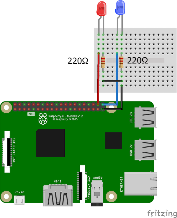
Circuit Diagram and Explanation
The circuit diagram is very simple. We just have to connect two LEDs to GPIO 20 and 21 on our Raspberry Pi using 220-ohm resistors. Connect the pins to the positive side of each LED and connect the negative side of each LED with the 220 ohm resistors to the ground.
Full Python Code
The Python code for controlling the Raspberry Pi’s GPIO pins through the GUI app can be found below. Copy and paste this code in a new file and save it with the filename extension: .py (for example, GUItest.py). Make sure you are in the same directory and then run the program from the terminal with the command python GUItest.py.
import Tkinter as tk
import RPi.GPIO as GPIO
from time import sleep
GPIO21 = 21
GPIO20 = 20
GPIO.setmode(GPIO.BCM)
GPIO.setup(GPIO21, GPIO.OUT)
GPIO.setup(GPIO20, GPIO.OUT)
master = tk.Tk()
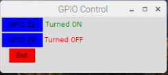
master.title("GPIO Control")
master.geometry("300x100")
GPIO21_state = True
GPIO20_State = True
def GPIO21button():
global GPIO21_state
if GPIO21_state == True:
GPIO.output(GPIO21, GPIO21_state)
GPIO21_state = False
ONlabel = tk.Label(master, text="Turned ON", fg="green")
ONlabel.grid(row=0, column=1)
else:
GPIO.output(GPIO21, GPIO21_state)
GPIO21_state = True
ONlabel = tk.Label(master, text="Turned OFF", fg="red")
ONlabel.grid(row=0, column=1)
def GPIO20button():
global GPIO20_State
if GPIO20_State == True:
GPIO.output(GPIO20, GPIO20_State)
GPIO20_State = False
OFFlabel = tk.Label(master, text="Turned ON", fg="green")
OFFlabel.grid(row=1, column=1)
else:
GPIO.output(GPIO20, GPIO20_State)
GPIO20_State = True
OFFlabel = tk.Label(master, text="Turned OFF", fg="red")
OFFlabel.grid(row=1, column=1)
ONbutton = tk.Button(master, text="GPIO 21", bg="blue", command=GPIO21button)
ONbutton.grid(row=0, column=0)
OFFbutton = tk.Button(master, text="GPIO 20",bg="blue" , command=GPIO20button)
OFFbutton.grid(row=1, column=0)
Exitbutton = tk.Button(master, text="Exit",bg="red", command=master.destroy)
Exitbutton.grid(row=2, column=0)
master.mainloop()
Code Walkthrough
Let's take a look at the code and see what each section does for the project as a whole.
First of all, we imported the required libraries for this project. The Tkinter library helped us create the GUI app and the RPi.GPIO library controls the GPIO pins of Raspberry Pi.
import Tkinter as tk
import RPi.GPIO as GPIO
from time import sleep
Then we initialized GPIO pins 21 and 20 for our LEDs using BCM pin numbering and declaring these pins as output.
GPIO21 = 21
GPIO20 = 20
GPIO.setmode(GPIO.BCM)
GPIO.setup(GPIO21, GPIO.OUT)
GPIO.setup(GPIO20, GPIO.OUT)
After that, we created the Tk root widget. There can only be one root widget and it must be created before any other widgets.
Then we renamed the title of this window and defined its size.
master = tk.Tk()
master.title("GPIO Control")
master.geometry("300x100")
When the GPIO 21 button is pressed, it will look for the previous state. If the previous state is true (high state), it will make it false (low state), and vice versa.
There is also a label beside the button that will tell us if the LED is HIGH or LOW.
def GPIO21button():
	global GPIO21_state
	if GPIO21_state == True:
		GPIO.output(GPIO21, GPIO21_state)
		GPIO21_state = False
		ONlabel = tk.Label(master, text="Turned ON", fg="green")
		ONlabel.grid(row=0, column=1)
	else:
		GPIO.output(GPIO21, GPIO21_state)
		GPIO21_state = True
		ONlabel = tk.Label(master, text="Turned OFF", fg="red")
		ONlabel.grid(row=0, column=1)
The GPIO 20 button works in a similar way:
def GPIO20button():
	global GPIO20_State
	if GPIO20_State == True:
		GPIO.output(GPIO20, GPIO20_State)
		GPIO20_State = False
		OFFlabel = tk.Label(master, text="Turned ON", fg="green")
		OFFlabel.grid(row=1, column=1)
	else:
		GPIO.output(GPIO20, GPIO20_State)
		GPIO20_State = True
		OFFlabel = tk.Label(master, text="Turned OFF", fg="red")
		OFFlabel.grid(row=1, column=1)
In the end, we created three buttons. Two of them control GPIO pins 20 and 21 and the third is the exit button.
ONbutton = tk.Button(master, text="GPIO 21", bg="blue", command=GPIO21button)
ONbutton.grid(row=0, column=0)

OFFbutton = tk.Button(master, text="GPIO 20",bg="blue" , command=GPIO20button)
OFFbutton.grid(row=1, column=0)

Exitbutton = tk.Button(master, text="Exit",bg="red", command=master.destroy)
Exitbutton.grid(row=2, column=0)
More Python Projects