In this tutorial, learn how you can utilize Raspberry Pi Zero and EduBlocks to create a tone generator!
The Raspberry Pi Zero WH is a versatile single-board computer (SBC) that can produce tones using a few lines of code. You can easily build a tone generator using a few off-the-shelf electronic components.
In this tutorial, I will show you how you can use an 8-pin power amplifier to amplify the frequency-based tone generated by the Pi Zero. Additionally, the code created to generate the tones is built using the gpiozero library EduBlocks so you will also learn how to view the equivalent gpiozero Python code created in the EduBlocks programming environment.
Required Hardware
To build the Pi Zero WH Tone generator, you will need the following components:
Before diving into the project build, let’s briefly review the basics of the LM386 power amplifier IC.
The LM386 Power Amplifier IC
In order to hear Pi Zero’s audible tones, you need an audio amplifier. There are a variety of audio amplifier circuits available for this application.
An audio amplifier can be built using several discrete transistors cascaded to increase the amplification gain of the circuit to hear the Pi Zero WH’s computer-generated tones. However, a less complex and more efficient solution to hearing audio signals is to use a LM386 power amplifier IC.
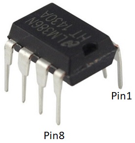
Figure 1. The LM386 Power Amplifier IC
The LM386 power amplifier is an 8-pin IC that can amplify a low audio signal to an appropriate audible sound level. It can also increase low signals based on an amplification gain factor.
The amplification gain of the LM386 can range from 20 to 200. Internally, the amplification gain defaults to 20 based on a 1.35KΩ resistor. To change the gain externally, a resistor placed across pins 1 and 8 makes the adjustment. With the appropriate resistor, an amplification gain of 200 can be achieved externally. The LM386 PA has a current amplifier capable of driving speaker loads ranging from 4 ohms (Ω) to 32Ω.
Additionally, the power supply voltage range is flexible. An operating voltage range of +4V to +15VDC provides proper electrical function to the LM386.
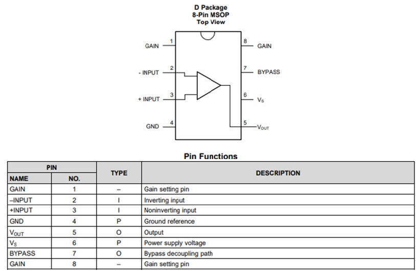
Figure 2 shows the LM386’s pinout.
Figure 2. The LM386 pinout with descriptions
With the LM386, a variety of devices such as Big Ears, light and sound detectors, and signal conditioning-amplification circuit interfaces are possible. Besides detection and signal conditioning circuits, the LM386 PA IC is suitable for creating 8- and 16-watt audio amplifiers. To find additional electrical specifications and amplifier circuits, check out the LM386 datasheet.
Wiring the LM386 to the Raspberry Pi Zero
In order to hear sounds from the Pi Zero WH, you need to wire the LM386 to the Pi Zero and a volume control to the LM386. The volume control adjusts the Pi Zero’s output signal amplitude by wiring the volume control between the Pi Zero’s output pin and the LM386’s input pin.
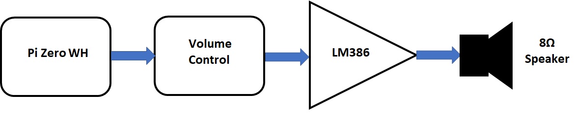
Figure 3 shows a basic system block diagram of the volume control placement between the Pi Zero and the LM386. These are the three key components of the tone generator.
Figure 3. The Pi Zero WH tone generator system block diagram
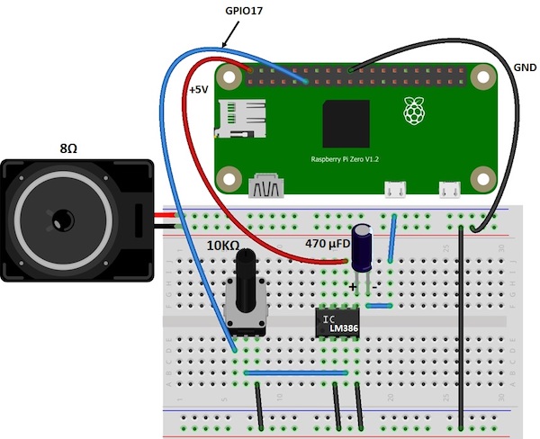
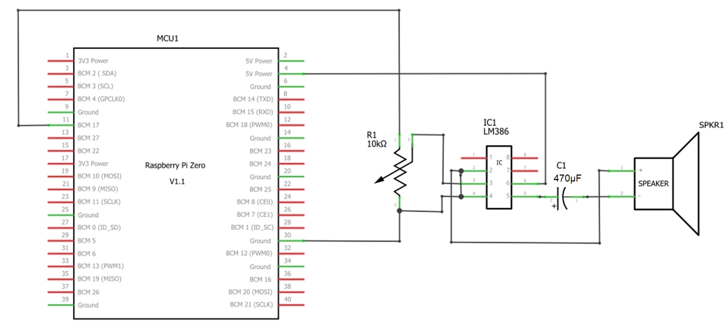
You can take the electronic components provided in the materials list and arrange them on the solderless breadboard as shown in the electrical wiring diagram.
Figure 4. The Pi Zero WH tone generator electrical wiring diagram.
The 470μFD electrolytic capacitor leads as shown in Figure 4 are polarized. Therefore, you must place the capacitor as shown in the electrical wiring diagram to ensure proper operation of the LM386. As a reference, the equivalent electronic circuit schematic diagram of the Pi Zero WH tone generator is shown in Figure 5.
Figure 5. The Pi Zero WH Tone Generator electrical wiring diagram.
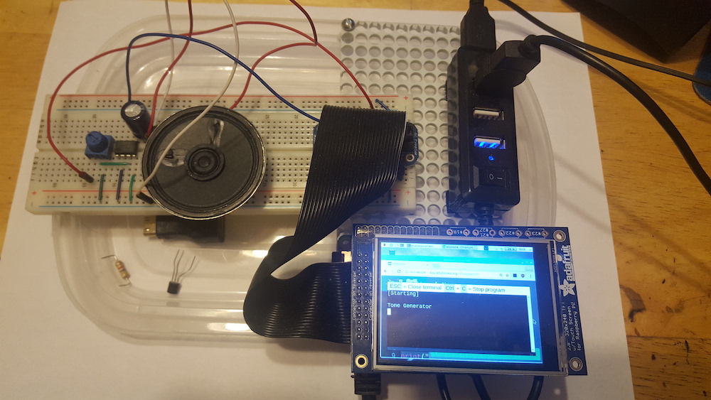
Figure 6 shows an example of the Pi Zero completely wired to the LM386.
Figure 6. The Pi Zero WH SBC wired to the LM386 PA IC.
With the Pi Zero WH electrically wired to the LM386 PA IC, it’s time to code the tone generator with EduBlocks. If you are new to EduBlocks, read how to install EduBlocks onto Raspberry Pi Zero before proceeding.
EduBlocks Tone Generator Code
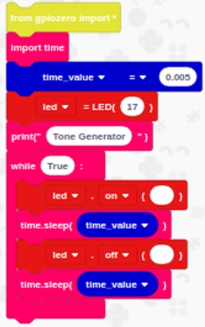
The Tone Generator Code is primarily an LED Flasher, whereby you control the sound by changing the on and off time values.
The output flash rate at pin GPIO17 of the Pi Zero produces a series of pulses or a squarewave. Open a new programming window in EduBlocks, and select the blocks shown in Figure 7.
Figure 7. The tone generator code built in EduBlocks.
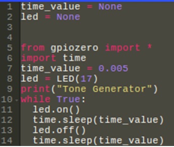
You can view the equivalent Python code by selecting the “code” button on the programming window.
After clicking the button with your mouse, you will see the equivalent Python code on the screen. The core of the code uses the gpiozero library. The gpiozero library utilizes Python and allows you to rapidly create physical computing devices with a Raspberry Pis.
Figure 8. The equivalent Python Tone Generator Code.
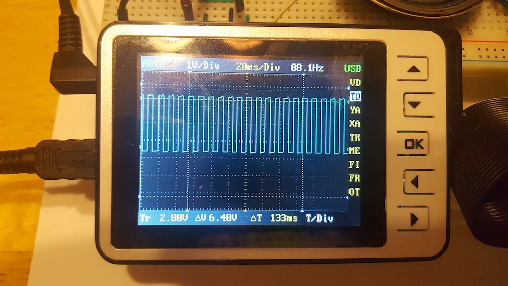
As seen in Figures 7 and 8, you can adjust the tone or sound of the generator by changing the time value. You can create low or high tones by changing the value accordingly. time_value shown in Figures 7 and 8 produce a tone with a frequency of 88.1Hz.
Figure 9. An 88.1 Hertz (Hz) tone produced with a time_value of 0.005.
You can experiment with your new tone generator by changing the time_value. If you’d like to add something more to your build, you can add an LED with a series limiting resistor to provide a visual effect.