Discover how to rotate an LCD touchscreen mounted to a Raspberry Pi or Pi Zero W. Learn the basics of an TFT LCD Screen.
In this hands-on tutorial project, you will learn how to rotate an LCD touchscreen mounted to a Raspberry Pi or Pi Zero W. In addition, you will be introduced to the operation of the TFT LCD screen in this tutorial project.
I’ll be using the Pi Zero W in this particular example to illustrate this simple technique, but the tutorial project techniques presented will work with any type of Raspberry Pi.
How a TFT LCD Works
A thin film transistor or TFT liquid crystal display (LCD) is a variety of LCD technology that uses thin film transistors to improve the visual quality of screens.
The visual quality of an LCD is improved by using a TFT-capacitor pixel driver circuit. The pixel or picture element consists of an organic light emitting diode or OLED component. The visual quality of an OLED is superior to the traditional LCD. The operation of an OLED is like that of general purpose (GP) silicon (Si) diode or an ordinary LED.
A GP Si diode or traditional LED uses n-type and p-type doping semiconductor materials. The doping has impurities which help with the GP Si diode and LED conductivity capabilities in an electrical circuit. Although this semiconductor structure works well in basic visual indicators and displays, when used in an array the quality is not as sharp in image resolution.
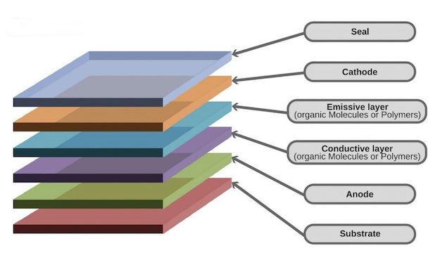
OLEDs use organic molecules to produce their n-type and p-type semiconductor layers. Figure 1 shows the construction of a typical OLED.
Figure 1. The construction of a typical OLED
A typical OLED is made up of six different n-type and p-type semiconductor layers. These multiple layers improve the image resolution quality of the display or screen. To turn ON and OFF the OLED based pixel, a TFT-capacitor driver circuit is used.
To turn ON or OFF an OLED, an electronic driver circuit is required. The electronic OLED driver circuit is simple in design and consists of two primary components: a TFT and a capacitor. The TFT LCD consists of an array of electronic OLED driver circuits that are selectable by a microcontroller.
The electronic OLED driver circuit has two input controls: data and switch select. The switch select enables the electronic OLED driver circuit by biasing the TFT. Biasing is an electrical circuit function of providing the proper DC operating voltage to ensure the TFT turns ON correctly. The data input control turns the TFT ON or OFF. Upon the TFT switch being biased and turn ON, a control signal enables the second the TFT which sources current from the power supply (VDD).
The sourcing current from the power supply biases the OLED, thereby turning the optoelectronic component ON. Optoelectronics is the combining of electronics with optical components. The optical component of the OLED is the light emitting organic (polymer) material.
To ensure the TFT is adequately turned ON, a simple charge pump circuit is used. The TFT is primarily a field effect transistor (FET) variant which has an internal gate capacitance. To overcome this internal gate capacitance, an external capacitor is used to bias the FET properly. In this biasing scheme, the external gate capacitor will have a higher charge voltage as compared to the internal gate capacitance of the TFT.
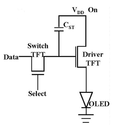
A simple TFT-capacitor OLED (pixel) driver circuit is shown in Figure 2. The individual electronic pixel driver circuits are arranged to make a TFT array. This array allows selecting multiple pixels, thereby creating a high-resolution image on the TFT LCD screen.
Figure 2. A typical TFT-capacitor pixel driver circuit
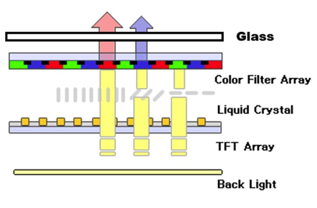
The construction of the TFT LCD touchscreen consist of layering several optoelectronic components together. The layered optoelectronic components consist of a backlight, the TFT array, liquid crystal, color filter array, and the glass. To display the image as chromatic, a color filter array is used. The backlight allows the LCD to properly display the images on the TFT LCD screen. Figure 3 shows the construction of a TFT LCD screen.
Figure 3. A typical TFT LCD Screen
Now that you understand how a TFT LCD touchscreen works, you are ready to build the project.
Adding the TFT touchscreen to the Pi Zero W
You are ready to add the TFT LCD touchscreen to the Pi Zero W. The orientation of the TFT LCD touchscreen is important. Improperly mounting the touchscreen can possibly damage the optoelectronic device as well as the Pi Zero W.
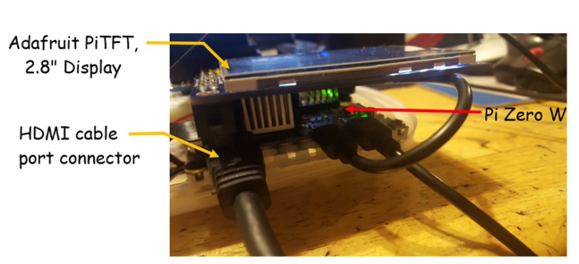
Mount the TFT LCD touchscreen by placing the device over the HDMI cable port connector. Then align the TFT LCD touchscreen’s dual female connector with the male pins mounted on the Pi Zero W. Apply light pressure on top of the TFT LCD touchscreen until the dual female connector is inserted on top of the Pi Zero W male pins.
Figure 4 shows the final mounting of the TFT LCD touchscreen onto the Pi Zero W SBC.
Figure 4. Properly mounting the TFT LCD touchscreen (Adafruit PiTFT) onto the Pi Zero W
Congratulations, you have successfully attached the TFT touchscreen to the PI Zero W SBC. In the next step of the tutorial, you will install the TFT touchscreen software onto the Pi Zero W.
Installing the Adafruit PiTFT Software
The next step in the tutorial project is to install the Adafruit PiTFT software onto the Pi Zero W.
Your Pi Zero W should be connected to a secure wireless network for obtaining the Adafruit PiTFT files over the internet. Use the LXTerminal that comes packaged with the Raspbian-Debian linux distro to obtain the PiTFT files.
You can also use a communication terminal like Putty or TeraTerm to secure shell (SSH) into the Pi Zero W. SSH allows you to operate your Pi Zero W without having an HDMI monitor attached to it. The desktop PC VGA monitor or the laptop computer’s screen will be used to interact with the Pi Zero W.
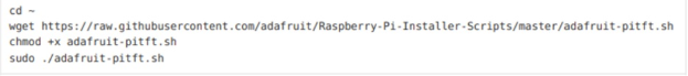
The photographs presented show the Adafruit PiTFT software being installed using the SSH method. Again, the Linux commands will work using the LXTerminal. On your screen at the prompt type in the following Linux commands.
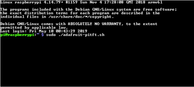
After typing the chmod +x adafruit-pitft.sh command follow, press the ENTER key. You will now install the PiTFT software onto the Pi Zero W. Type the sudo ./adafruit-piTFT.sh command after the prompt as shown in Figure 6.
Figure 6. Installing the PiTFT software onto the Pi Zero W
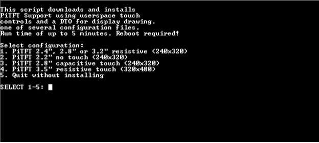
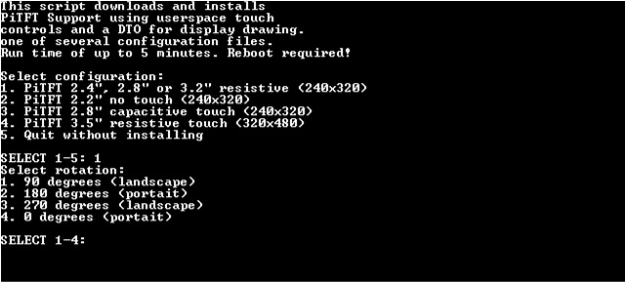
The following PiTFT configuration menu will be displayed on the screen.
Figure 7. PiTFT configuration menu
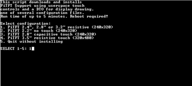
Use the following images to rotate the screen 180° for a portrait orientation.
Figure 8. Enter 1 for screen size selection.
After entering the screen size, the rotation options menu will be displayed.
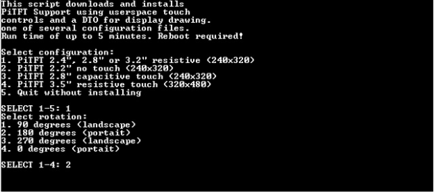
Figure 9. Four options to rotating the TFT LCD touchscreen
You will enter number two for portrait orientation.
Figure 10. Enter 2 for portrait orientation of 180° screen rotation
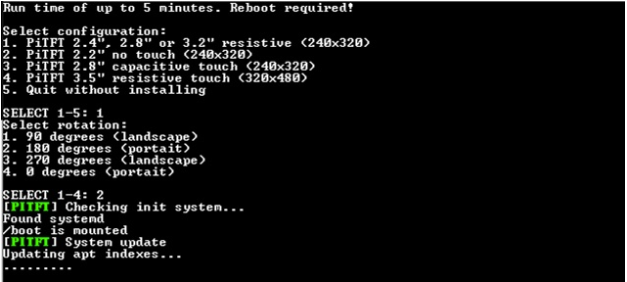
After entering number 2 for the portrait orientation, the PiTFT installation files will be installing on your Pi Zero W SBC.
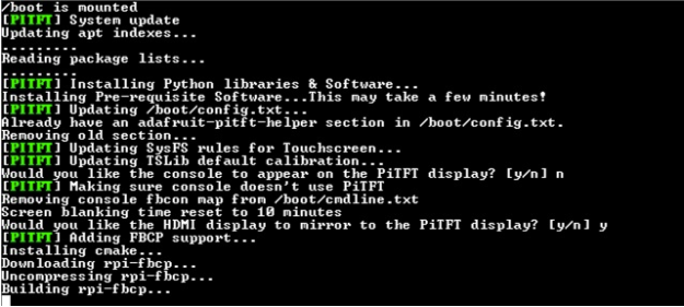
Figure 11. PiTFT files being obtained from the Adafruit server
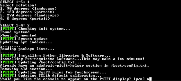
You will then enter “n” for no console mode display on TFT LCD touchscreen.
Figure 12. Prompt asking if you would like the PiTFT to display in console mode
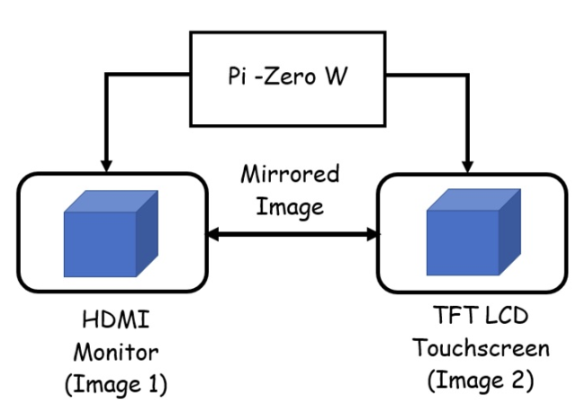
The next prompt to be presented asks if you would like the HDMI image to be mirrored with the TFT LCD touchscreen. This is an optional feature. This feature is quite useful for debugging of code or remote and local location display applications. Figure 13 shows the concept of mirroring displays.
Figure 13. Mirrored image concept. HDMI Monitor and TFT LCD touchscreen will have the same displayed image on both display devices.
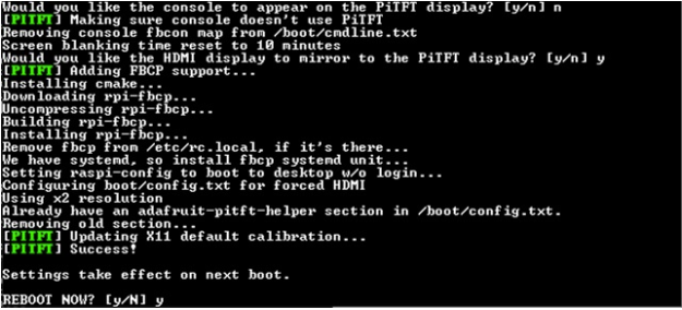
After entering “y” for the mirroring feature, the final installation and configuration of the TFT files will commence.
Figure 14. Final Installation and files configuration for PiTFT software.
The final step is to reboot the Pi Zero W to accept the portrait orientation changes.
Figure 15. The Pi Zero W will be rebooted to accept changes for the portrait TFT LCD touchscreen orientation
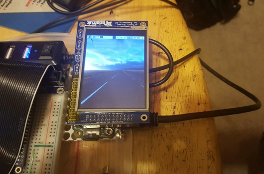
The Pi Zero W will go into reboot mode. After completing the operation, the TFT LCD touchscreen will display images in portrait orientation.
Figure 16. The TFT LCD Touchscreen displaying in portrait orientation
You have successfully rotated your TFT LCD touchscreen’s orientation to portrait display. You can change to the original landscape orientation by repeating the procedure again.
OLED Applications: The Metaverse Experience!
You can continue exploring OLED applications and TFT LCD Touchscreens through Augmented Reality (AR).
You can experience this AR tutorial by downloading and installing the Metaverse Augmented Reality App on your Android or iOS mobile device. Once you have the App downloaded and installed, open it on your mobile device. Point your mobile device’s camera at the QR code and touch the “Scan QR code” text with your finger. In a few seconds, the Metaverse AR experience App will be on your device. Happy learning!