Learn how to convert analog signals to digital input via this project connecting an MCP3008 to a Raspberry Pi!
Depending on the model, Arduinos have a number of digital pins, analog inputs, and pulse width modulation (PWM) digital pins. However, the Raspberry Pi only accepts digital inputs. One way to read analog input is to use analog to digital converters — the MCP3008 being one of the most popular among them. The MCP3008 uses SPI to talk to the Raspberry Pi and provides eight pins for analog input.
In this tutorial, I’ll show you how to connect the MCP3008 to a Raspberry Pi. Before diving in, collect the necessary hardware.
In this tutorial, I’ll show you how to connect the MCP3008 to a Raspberry Pi. Before diving in, collect the necessary hardware.
Required Hardware
- Raspberry Pi
- Breadboard
- Raspberry Pi Cobbler
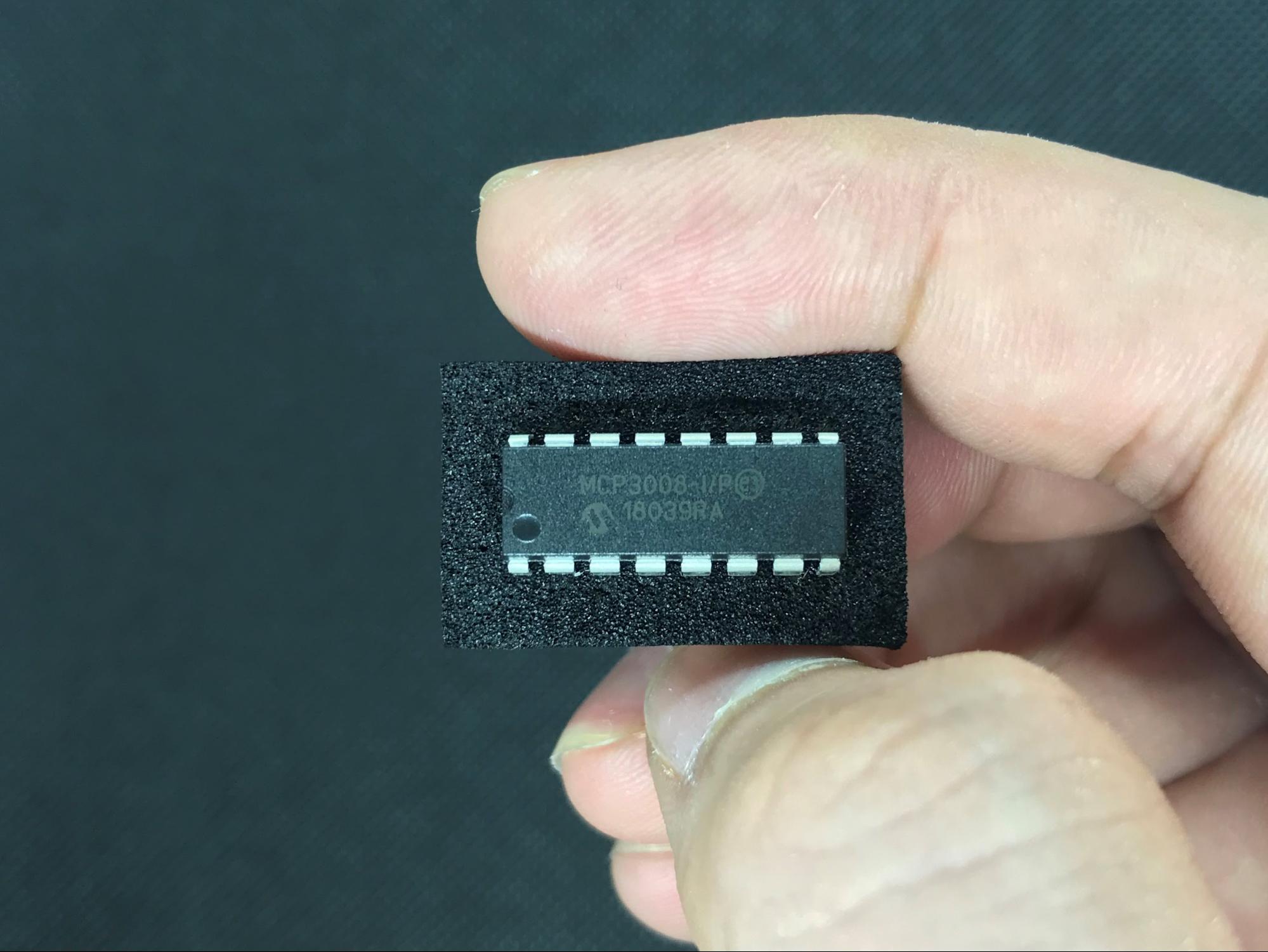
- MCP3008 8-channel, 10-Bit analog-to-digital converter (ADC)
- Light Dependent Resistor (LDR)
- 10 KΩ resistor
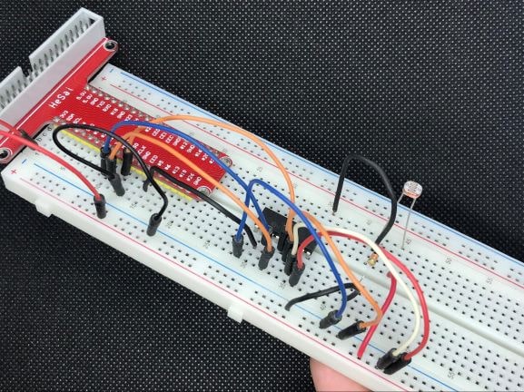
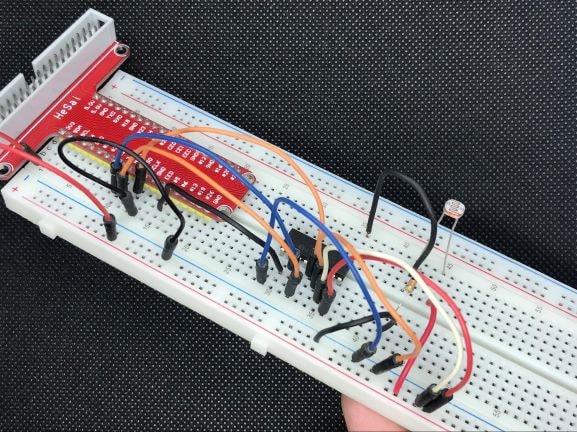
The hardware placed on a breadboard.
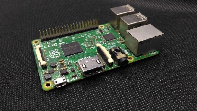
The Raspberry Pi is an SBC and is more powerful than most Arduino models, because of its bigger RAM, built-in Wi-Fi and Bluetooth capabilities, and a powerful processor. It also comes with 40 GPIO pins but has a few extra I2C, SPI, and UART connections available. GPIO pins are multipurpose and can be in an ON or OFF state. The newer versions of Raspberry Pi also include dual micro HDMI ports.
Prototyping with a Pi can be made easier with the help of Raspberry Pi Cobbler by reducing time and preventing short circuits with a breadboard-friendly interface. All you have to do is connect one end to your Raspberry Pi and you’re ready to access the Raspberry Pi GPIO, including the I2C and SPI pins.
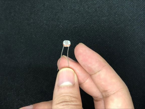
LDR, also known as a photoresistor/photocell/photoconductor, is a type of resistor that has a variable resistance that changes with the light intensity that falls upon it. When the light falls on the resistor, the resistance changes.
The light-dependent resistor.
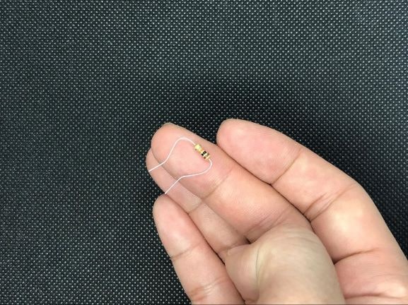
The color code for the 10 KΩ/10000 Ω resistor is brown, black, orange, and gold. This type of resistor has a four-band color code, but it also has the tolerance of a gold band ± 5%.
What is an MCP3008?
The MCP3008 is a high performance, low-power 10-bit analog to digital converter and is applicable for embedded control applications like data acquisition, instrumentation and measurement, industrial PCs, multi-channel data loggers, robotics, motor control, industrial automation, smart sensors, portable instrumentation, and home medical appliances.
MCP3008 Features
- 10-bit resolution
- SPI interface
- -40 to +85°C temperature range
- Eight single-ended channels
Assembling the Hardware
I am using an old Raspberry Pi 2B that my cobbler is compatible with. If you are using different versions of Raspberry Pi, chances are that the cobbler you need may also have different pins. Make sure to look for compatible Raspberry Pi versions for your cobbler of choice.
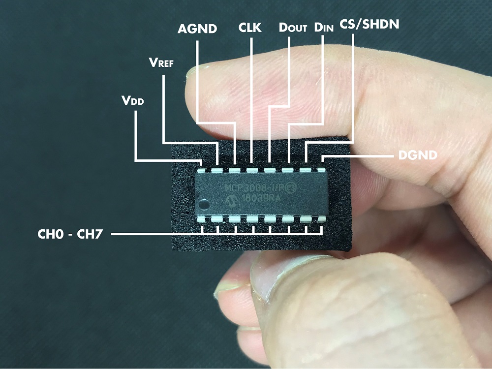
Let’s identify the underlying pins of our MCP3008 ADC. We will be using the VDD, VREF, AGND, CLK, DOUT, DIN, CS/SHDN, DGND, and CH0 pins. The MCP3008 has eight channels. Depending on your experiment or the number of sensors that you want for different projects, you can use all of these channels. In this tutorial, we will be using one.
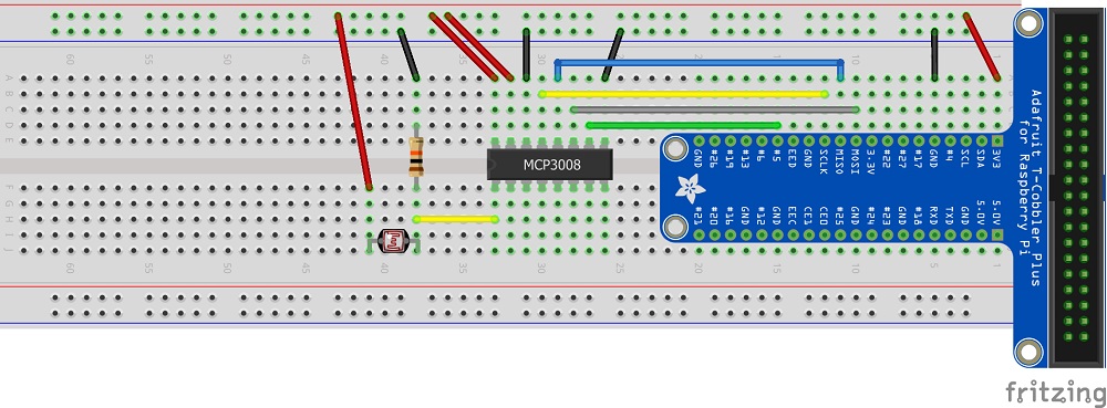
Next, place all the materials that are needed in the breadboard. We will be using the 3v3 pin of our GPIO, as well as ground, SPI ( MOSI, MISO, SCLK ), and Pin 5 for CS.
Here are the connections:
MCP3008 | Connection
|
|---|
VDD | 3.3 V (Red)
|
VREF | 3.3 V (Red) |
AGND | GND (black) |
CLK | SCLK (yellow) |
DOUT | MISO (blue) |
DIN | MOSI (gray) |
CS | Pin 5 (green) |
DGND | GND (black) |
Next, connect the LDR sensor. One pin of the LDR goes to the 3.3V power line and the second pin is connected to the MCP3008 CH0 pin, which is then connected to the GND with the 10 KΩ resistor.
Here is the full circuit diagram showing all of our connections.
Required Software
The Raspberry Pi needs to be running the latest version of Raspbian. Run the following commands to make sure your installation packages are up to date:
sudo apt-get update -y
sudo apt-get upgrade -y
Now install the following dependencies for your project.
PIP, or the Python Package Installer, can be used to install packages from the Python package index and other indexes. Install it using the following command:
sudo apt-get install python3-pip
Next, install adafruit-blinka:
sudo pip3 install adafruit-blinka
To use the MCP3008, you need to install the CircuitPython library for the MCP3xxx series of analog-to-digital converters:
sudo pip3 install adafruit-circuitpython-mcp3xxx
With all the dependencies downloaded for the libraries needed in this project, we can use the sample Python code from Adafruit’s GitHub repository to read the values of the LDR sensor via MCP3008. Note that this code is written in CircuitPython, developed by Adafruit. CircuitPython is based on the Python programming language but with extensive support for hardware devices.
Here are the lines that print the values in the code:
print('Raw ADC Value: ', chan0.value)
print('ADC Voltage: ' + str(chan0.voltage) + 'V')
Save the downloaded code in a text file with an extension .py (example.py) and run it from the terminal: python example.py.
To successfully run the program, make sure you are in the same directory in the terminal.
