Learn how to interface the TCS34725 RGB color detector with a Raspberry Pi Zero and use color in your next project!
They say that colors speak louder than words, but did you know that colors also have their own words and language?
The color RGB and hex is a model representation of red, green, and blue light added together. These give the details of how much red, green, or blue is present in color, while hex is the short representation of RGB. In this tutorial, I’ll show you how to interface the TCS34725 RGB color detector with a Raspberry Pi Zero.
Required Hardware
- 1 TCS34725 RGB Sensor
- 1 Raspberry Pi Zero
- 1 16x2 LCD Module
- 1 10k Potentiometer
- 1 10K Ohms Resistor
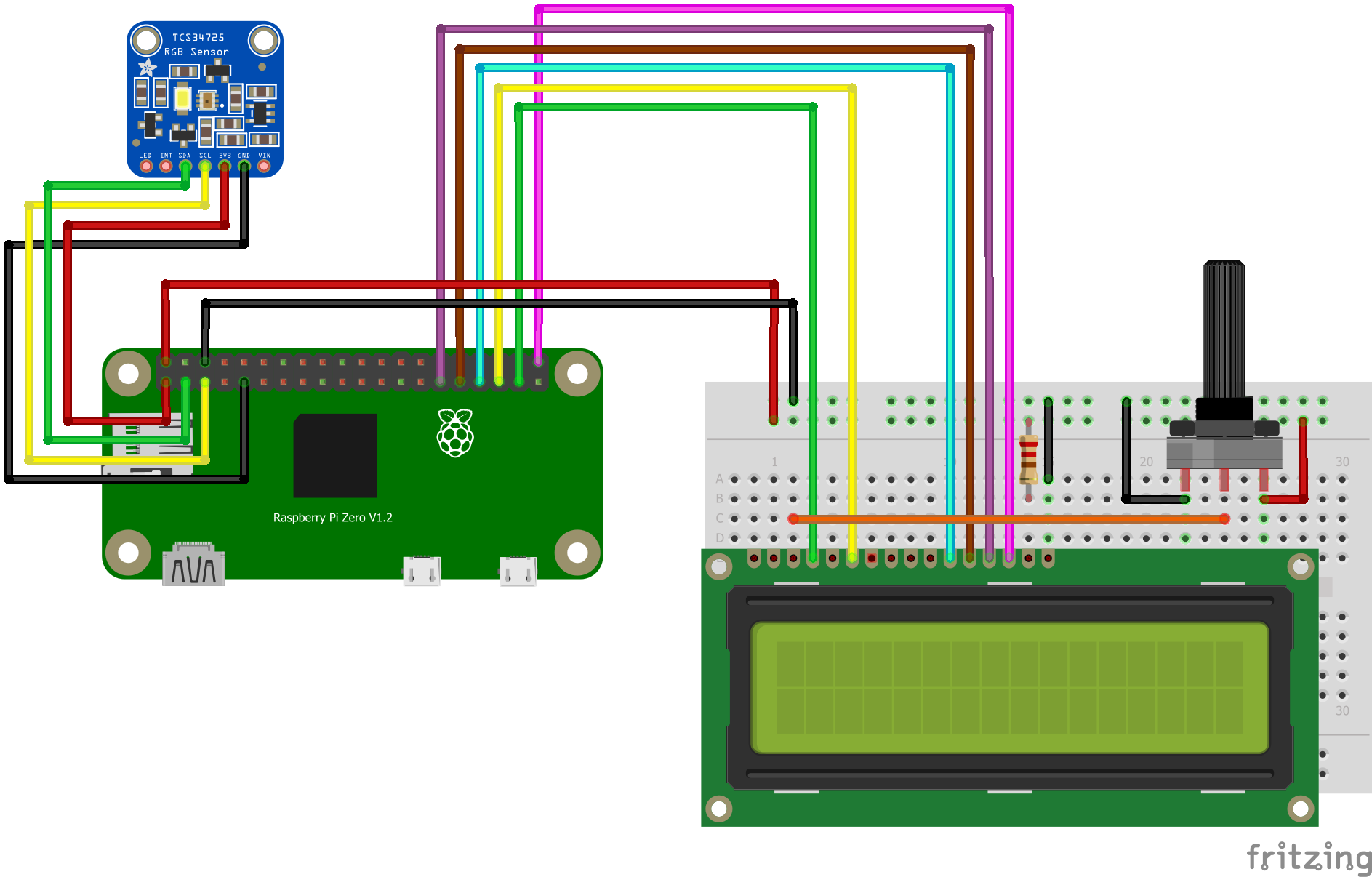
Circuit Diagram
How the TCS34275 Works With a Raspberry Pi
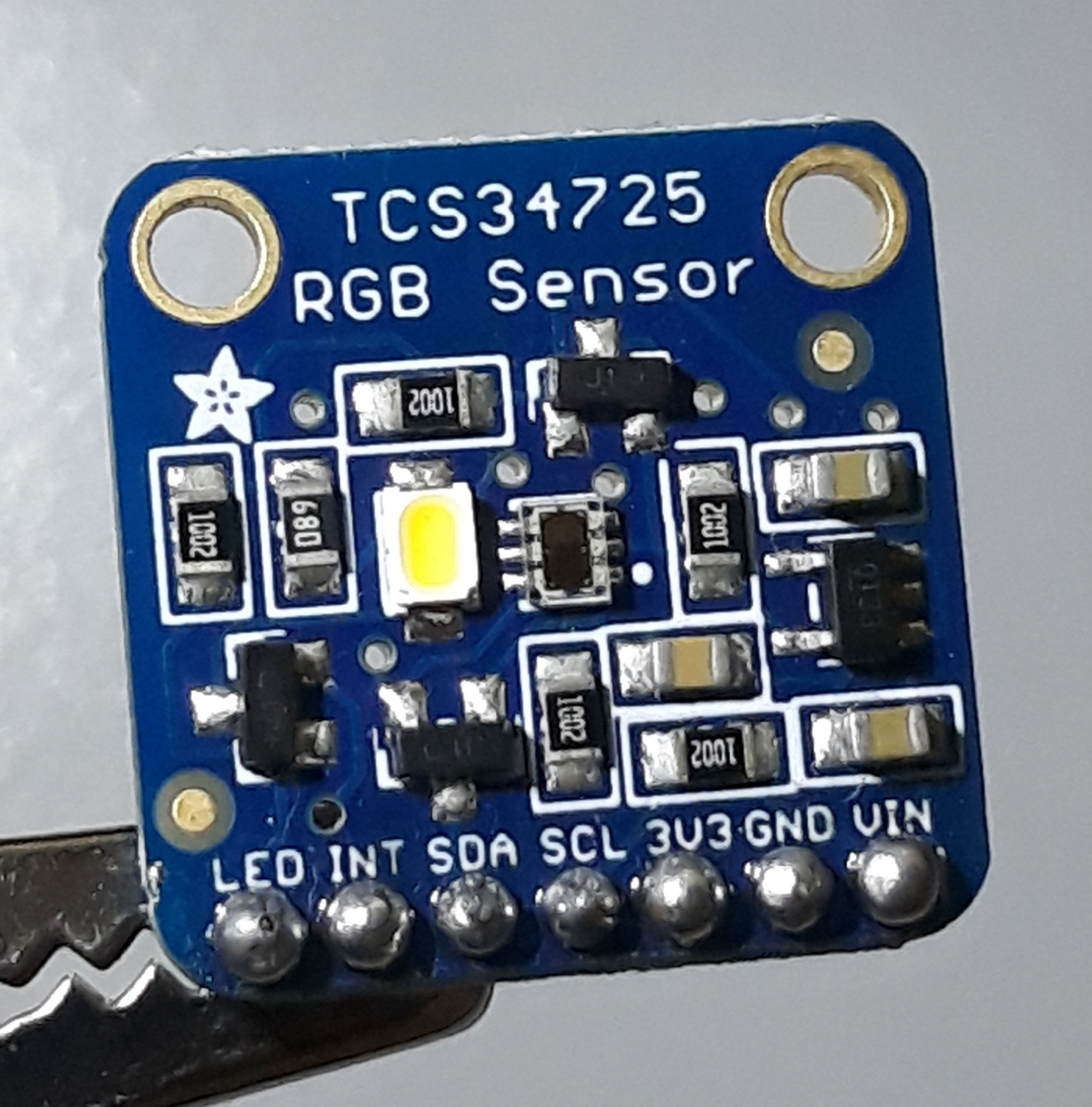
The color sensor used in this tutorial’s circuit is an Adafruit TCS34725 color sensor. It has a 3 x 4 photodiode array and four ADC converters to convert the light to photodiode current to a 16-bit digital value.
Raspberry Pi Zero W is set up as a headless Pi. It runs using the Raspbian Lite version OS without the graphical user interface, since the project is mostly using the Raspberry Pi Zero W to process the data gathered without the need of a graphical interface. An LCD 16x2 digital display is used to output the result in lieu of a GUI.
Note: This guide is based on a Raspberry Pi Zero W with a Raspbian headless setup, but can also work with full version of Raspbian OS.
Raspberry Pi Zero Setup
In the project, a headless or screenless setup will be used since we will be using a 16x2 LCD module instead of displaying the output to the display of the Raspberry Pi Zero W.
Before we proceed with interfacing the color sensor and LCD module, there are few steps that need to be done on the Raspberry Pi Zero W.
- First, set a headless booting for the Raspberry Pi Zero W.
- Before installing modules to the Raspberry Pi Zero W OS, always update and upgrade so there won’t be any errors later on.
$sudo apt-get update -y
$sudo apt-get upgrade -y
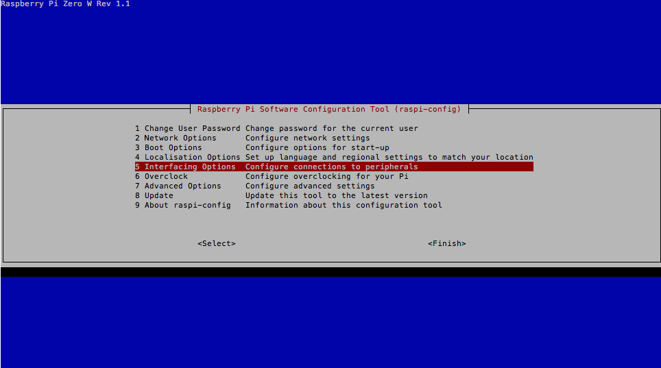
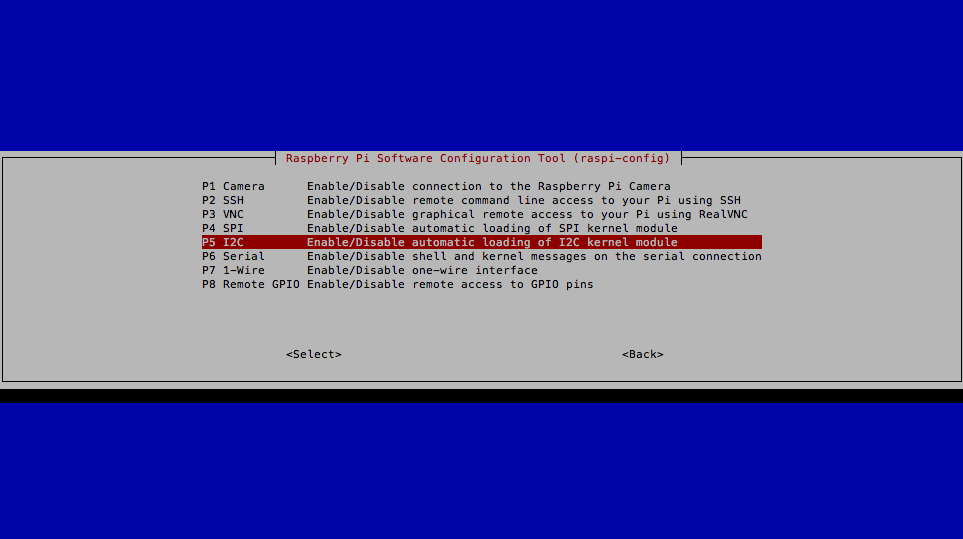
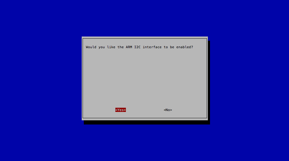
3. Enable the I2C interface by typing the following command in the terminal:
Select the interfacing option.
Reboot the Raspberry Pi Zero W for these commands to take effect by typing the following command:
Interfacing the Adafruit TCS34725
With the Raspberry Pi Zero W I2C interface enabled, interfacing the Adafruit TCS34725 color sensor using I2C connections is possible.
1. For the physical connection of the TCS34725 and Raspberry Pi Zero W, refer to the table below. Note that the Raspberry Pi Zero W must be turned OFF during the connection.
Pin Connections
TCS34725 | Raspberry Pi Zero W |
|---|
GND | Pin 9 (GND) |
3v3 | Pin 1 (3V3) |
scl | Pin 5 (GPIO3) |
sda | Pin 3 (GPIO2) |
2. Once the connections are done, turn-on and connect again to the device.
3. For this project, Python3 is used. To Install Python3, use the following command:
$sudo apt-get install python3-pip
4. Install git to clone libraries.
$sudo apt-get install git
6. After cloning the library, navigate to the Adafruit_CircuitPython_TCS34725 folder.
$cd Adafruit_CircuitPython_TCS34725
Install the setup.py using:
$sudo python3 setup.py install
Interfacing the 16x2 LCD Module
Use the table below to connect the 16x2 LCD module to the Raspberry Pi Zero and Potentiometer.
Pin Connection
16x2 LCD Module | Raspberry Pi Zero / Potentiometer |
|---|
VSS | GND |
VDD | +5V |
VE | Middle potentiometer pin |
RS | Pin 37 (GPIO 26) |
RW | GND |
E | Pin 35 (GPIO19) |
D0 | - |
D1 | - |
D2 | - |
D3 | - |
D4 | Pin 33 (GPIO 13) |
D5 | Pin 31 (GPIO 6) |
D6 | Pin 29 (GPIO 5) |
D7 | Pin 38 (GPIO 20) |
A+ | +5V |
K- | GND |
7. The library for the LCD module is supported by the GNU/Linux system for the Raspberry Pi, which can be installed locally from PyPI using the command below.
7. The library for the LCD module is supported by the GNU/Linux system for the Raspberry Pi, which can be installed locally from PyPI using the command below.
$sudo pip3 install adafruit-circuitpython-charlcd
Code
import time
import board
import adafruit_tcs34725
import busio
import digitalio
import adafruit_character_lcd.character_lcd as character_lcd

#intializeLCD
lcd_columns = 16
lcd_rows =2

lcd_rs = digitalio.DigitalInOut(board.D26)
lcd_en = digitalio.DigitalInOut(board.D19)
lcd_d7 = digitalio.DigitalInOut(board.D21)
lcd_d6 = digitalio.DigitalInOut(board.D5)
lcd_d5 = digitalio.DigitalInOut(board.D6)
lcd_d4 = digitalio.DigitalInOut(board.D13)

lcd = character_lcd.Character_LCD_Mono(lcd_rs, lcd_en, lcd_d4, lcd_d5, lcd_d6,lcd_d7, lcd_columns, lcd_rows)

#initializeColorSensor
i2c = busio.I2C(board.SCL, board.SDA)
sensor = adafruit_tcs34725.TCS34725(i2c)