Learn how to connect and control a DC servo motor with a Raspberry Pi Zero WH and some simple code!
Controlling a small DC servo motor with a Raspberry Pi Zero WH is quite easy. With a DC servo motor, you can create a variety of mechanical actuated devices such as paper animatronics, and linear actuators.
In this hands-on tutorial, you will learn how to wire a small DC servo motor to a Pi Zero WH. Once we have the hardware connected, I'll show you how to use the gpiozero library to create the Python code to operate your DC servo motor controller. Let's begin!
Required Hardware
- Pi Zero WH: MCU1
- Tactile Pushbutton Switch: S1
- DC Servo Motor: M1
- Solderless breadboard
- Jumper wires
DC Servo Motor Basics
Before discussing the project build, let's review how a DC servo motor works.
A DC servo motor is an electromechanical component that uses digital pulses to provide precision rotation. The construction of a servo motor consists of a DC motor attached to a servomechanism. The servomechanism allows for the production of motion at a significant level of energy with respect to the input setting.
Such a mechanism allows precision rotation to be achieved based on the internal feedback signal. A potentiometer mechanically attached to the DC motor using a gearing mechanism provides the internal feedback signal. A small proportional voltage is produced by the potentiometer. A small electronic control unit reads this proportional voltage thereby adjusting the DC motor to the correct rotational position.
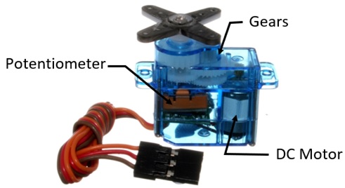
The pulse width modulation signal (PWM) provides the reference setting for the DC motor’s angular position. Figure 1 shows the inner components of a typical DC servo motor.
Figure 1. The internal components (servomechanism) of a typical DC servo motor.
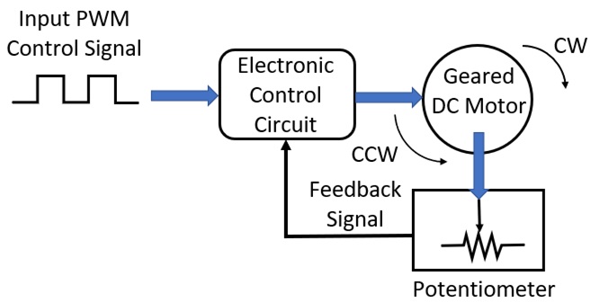
The block diagram shown in Figure 2 illustrates the servomechanism components and their system interconnection to each other.
Figure 2. System block diagram (SBD) for a typical DC servo motor.
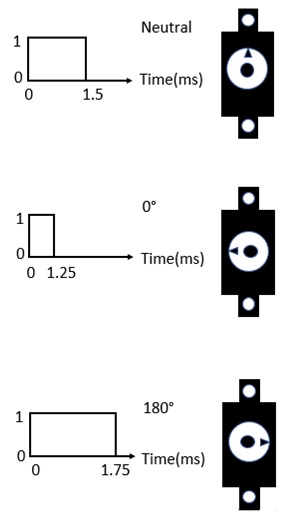
To set the servo motor’s shaft position, a pulse with a specified length is provided by a microcontroller. The servo motor’s electronic control circuit receives the PWM control signal approximately every 20 milliseconds (ms). The servo motor’s shaft rotation position is then set based on the control signal pulse. Figure 3 shows the servo motor’s shaft position with a discrete pulse value in ms.
Figure 3. Typical pulse widths with angular positions for controlling a DC servo motor.
With a basic knowledge of a DC servo motor, you are now ready to wire and control a DC servo motor with a Pi Zero WH SBC.
Wiring a DC Servo Motor to the Pi Zero WH
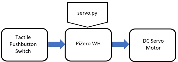
To build a simple DC servo motor controller, you will need three physical hardware components: a tactile pushbutton switch, a Pi Zero, and a small DC servo motor. Also, you need one software component, the servo.py Python code.
Figure 4 illustrates the DC servo motor controller system block diagram.
Figure 4. A Simple DC servo motor controller system block diagram.
With the SBD, you can create a simple electrical wiring diagram to wire your DC servo motor controller.
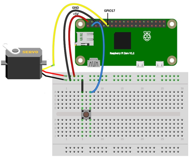
To create your DC servo motor controller electrical wiring diagram, you can use Fritzing. Figure 5 shows the electrical wiring diagram for wiring your DC servo motor to the Pi Zero.
Figure 5. Solderless breadboard for wiring a DC servo motor to a Pi Zero WH.
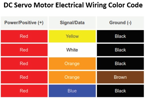
A DC servo motor has three wires: voltage supply (power), ground, and control (signal). The control signal and ground wires come in a variety of colors. Therefore, depending on your DC servo motor type use the following chart shown in Chart 1.
Chart 1 ensures the proper electrical wiring to the Pi Zero WH SBC is correct.
Chart 1. DC servo motor electrical wiring chart.
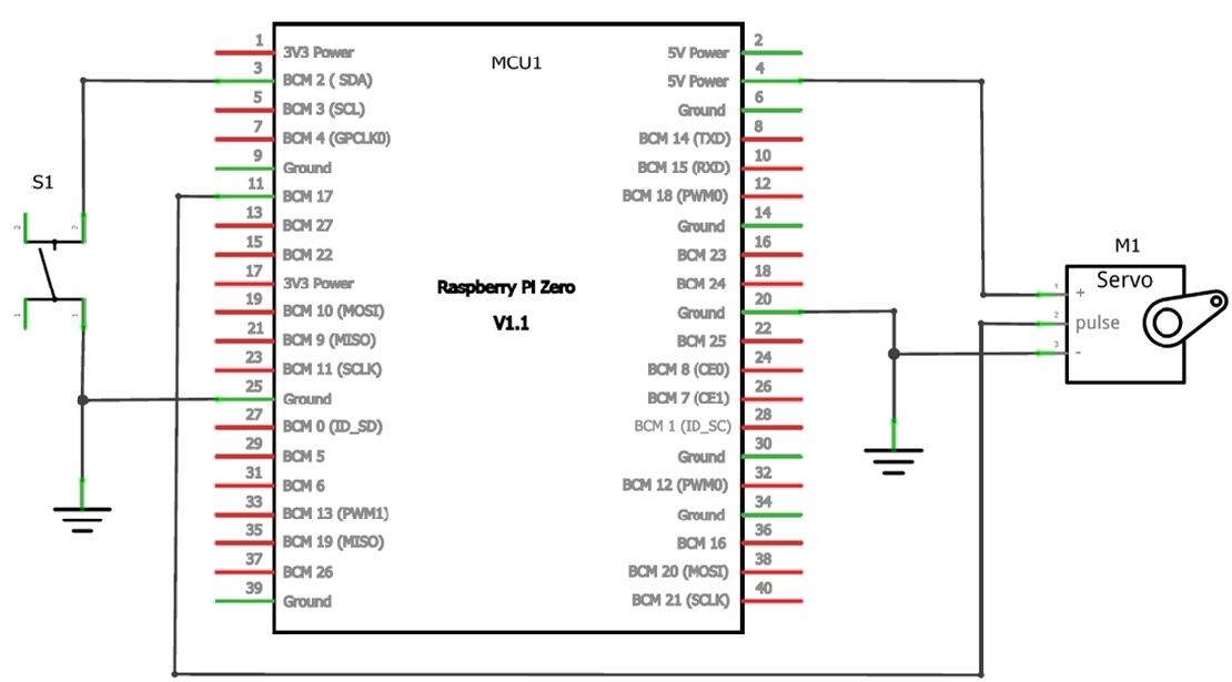
As an additional reference, the electronic circuit schematic diagram is shown in Figure 6. You can use the electronic circuit schematic diagram to wire the DC servo motor to the Pi Zero WH.
Figure 6. The simple DC servo motor controller circuit schematic diagram.
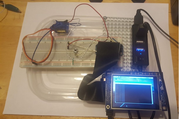
As an example of the final electrical wiring of the DC servo motor controller, Figure 7 shows my finished device.
Figure 7. A functioning Pi Zero WH DC servo motor controller built by the author.
Adding servo.py Code to the Pi Zero WH
With the wiring complete, you are now ready to add the Python code to make your build operational!
The servo.py Python code uses the gpiozero library to operate the electrically wired DC servo motor to the Pi Zero WH. The gpiozero library is packaged with the Pi Zero WH Raspbian Jessie linux distro.
Code the servo.py Python program using the lx terminal’s nano editor. To access the nano editor, type ($) sudo nano servo.py after the prompt. After you type the Linux command into the lx terminal, you will see a blank editor display on your monitor’s screen.
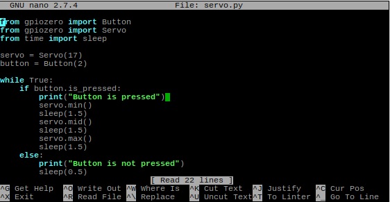
Next, type the code using Figure 8 to create the servo.py Python file.
Figure 8. Entering the servo.py Python code using the lx terminal.
After entering the code, exit out of the nano editor. To test the DC servo motor controller, type the following Linux command into the lx terminal: sudo python servo.py. The message "Button is not pressed" will scroll down your monitor’s screen as shown in Figure 9.
Figure 9. The servo.py code executing on the Pi Zero WH.
When you press and hold the tactile pushbutton switch, the DC servo motor will rotate between the min, mid, and max angular positions. You will also see the message "Button is pressed" scrolling down the monitor’s screen.
If the DC servo motor is not rotating or the messages are not scrolling down on your monitor’s screen, check the electrical wiring and Python code. After you find and correct the error, execute the code again.
As an experiment, you can change the sleep ( ) values and make note of the DC servo motor’s rotational behavior. Record your observations and happy experimentation!