Learn about physical computing and build a simple object detector with a light sensor and Raspberry Pi Zero W.
In How to Get Started With the Raspberry Pi Zero W, we explored the features and setup of the low-cost Linux single board computer (SBC). In this tutorial, learn about physical computing and how you can build a simple object detector with a light sensor and collect data using the Pi Zero W. Let’s start the tutorial with a discussion on PC.
What is Physical Computing?
Physical computing (PC) deals with building devices that can sense and respond to their environment using software and hardware. Interaction with a device or object is the primary goal of PC. The technology of PC is used by artists and designers for creating interactive art.
Mechatronics is an interdisciplinary field using electrical-electronics, mechanics, and embedded software to make mechanical systems more efficient and intelligent. Electronic sensors collect environmental data relating to positioning of mechanical parts or actuating assemblies. The embedded software will process this positioning data and make mechanical adjustments based on the logic embedded within the control code. Therefore, at the core of a Mechatronics system is PC.
Also, PC relies on electronic sensors to obtain physical stimuli such as light, temperature, pressure, and sound. Actuators such as motor and solenoids provide rotary and linear motion for PC devices. If a PC device needs visual indicators, electronic devices like LEDs, LCDs, gauges, and monitors are used to provide the effects. In addition, audible indicators or alarms can be achieved using speakers and buzzers. With your new knowledge in PC, you are now ready to learn how the simple object detector sensor works with a Pi Zero W.
How Does the Simple Object Detector Sensor Work?
The simple object detector is a PC device that senses light level changes. A photoresistor senses the light levels and sends the data to the Pi Zero W. The Python code that is embedded within the Pi Zero W’s microcontroller will display the values on an HDMI monitor.
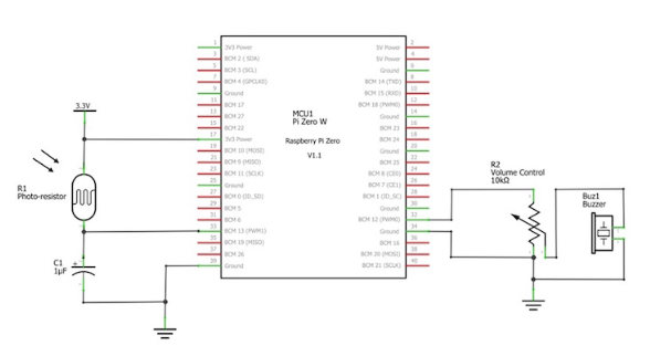
Since the Pi Zero W doesn’t have an internal analog to digital converter (ADC) to read the varying light level data, an electrolytic capacitor is used. The electrolytic capacitor is constantly charging and discharging by the varying current produced by the photoresistor. The data displayed on the HDMI is the charging and discharging voltage levels of the electrolytic capacitor based on the photoresistor's varying current. Figure 1 shows the electronic circuit schematic diagram for the simple object detector.
Figure 1. The object detector circuit diagram.
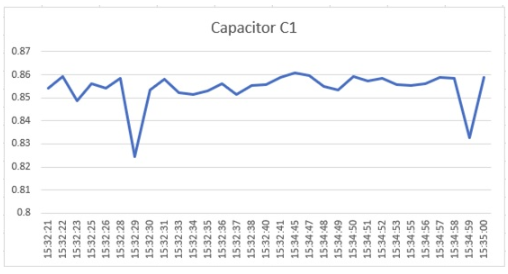
Figure 2 shows the charging and discharging plot for the 1µF electrolytic capacitor (C1) used in the object detector device.
Figure 2. The charging and discharging plot of the C1 electrolytic capacitor.
For the plot shown in Figure 2, the “x” axis is time with voltage being the “y” axis. With an understanding of how the light sensor circuit works, you are ready to build the PC based object detector.
Build the Simple Object Detector
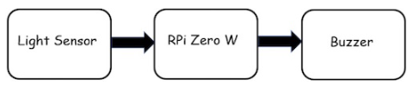
As you have learned from the previous discussion, the object detector has two main sections: a light sensor circuit and a microcontroller. The third section of the PC device is an audible output alarm. Therefore, the simple object detector has three main sections: a light sensor, a microcontroller, and an audible output alarm. Figure 3 shows the block diagram of the simple object detector.
Figure 3. The simple object detector block diagram.
You can build a simple object detector using a few electronic components and a PI Zero W. The electronic parts you will need to build the light sensing project are listed below.
- (1) piezo buzzer (Buz1)
- (1) 10 kilo-ohm (KΩ) trimmer or linear potentiometer (R2)
- (1) Photoresistor (R1)
- (1) 1microfarad (µF) electrolytic capacitor (C1)
- (1) Raspberry Pi Zero W
- (1) solderless breadboard
- Jumper wires
Note: Adafruit sells a Parts Pal kit (Product ID: 2975) that provides the electronic components for this project.
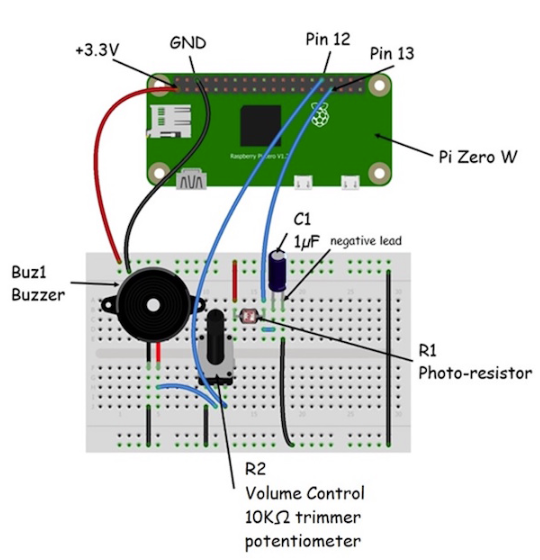
With the electronic parts on hand, you can build your simple object detector by using the electrical wiring diagram shown in Figure 4. The 1µF electrolytic capacitor is a polarized electronic component. You will see in Figure 4 the orientation of the electrolytic capacitor regarding the negative lead. If the electrolytic capacitor is incorrectly placed in the circuit, the PC device will not work. You will wire the negative lead to the ground rail or row as shown in Figure 4.
Figure 4. The electrical wiring diagram for the simple object detector.
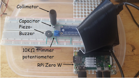
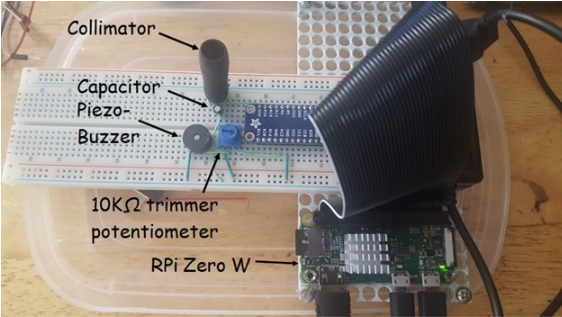
You will use 3 inch female/male jumper wires to electrically connect the Pi Zero W to the solderless breadboard as shown in Figure 4. Before powering the PC device, recheck your wiring for errors. With electrical wiring complete, you can then write the Python code for the simple object detector. Figure 5 shows the final project build of the simple object detector.
Figure 5. The complete simple object detector device.
To improve the object detection feature of the PC device, a simple collimator made from an ink pen gripping tube is placed over the photoresistor. The collimator will eliminate ambient light from the photoresistor while operating. Congratulations, you have successfully built the simple object detector PC hardware. You are now ready to code the PC detection feature using the Python coding language.
Figure 6. A collimator used to remove ambient light from the photoresistor.
The Object Detector Python Code
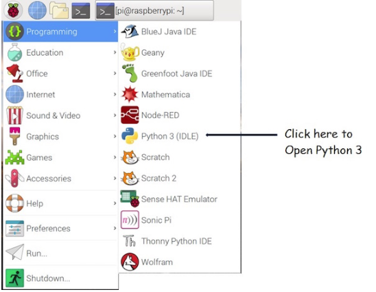
With the object detector electrical wiring complete, you will program (code) the Pi Zero W to read light level changes in Python coding language. Also, the Python code will sound an alarm when detecting an object. To code the application, open Python 3 software as shown in Figure 7.
Figure 7. Accessing Python 3 coding software from the Pi Zero W desktop.
With the coding software open, you will click on File > New File. Type in the following Python code:
from gpiozero import  LightSensor, Buzzer
from time import sleep, strftime, time

ldr = LightSensor(13)
buzzer = Buzzer(12)

with open("/home/pi/ldr_data2.csv", "a") as log:
    while True:
        if ldr.value == 0:
           buzzer.on()
           sleep(1)
           buzzer.off()
           sleep(1)
        else:
            buzzer.off()
            ldrsensor = ldr.value
            log.write("{0},{1}\n".format(strftime("%S"),str(ldrsensor)))
            print(ldr.value)
            sleep(1)
The code listing consists of three parts:
- Importing libraries
- Assigning variables
- The code loop
The libraries needed for the ldr_data.py code application is the gpiozero and time. The gpiozero allows you to access the Pi Zero W’s BCM2835 microcontroller general-purpose input-output (GPIO) pins, timers, counters, interrupts, communication ports, and pulse width modulation (PWM) resources.
The time library allows you to access the internal system clock functions of the ARM v7 processor. The ldr and buzzer are variable names assigned to the GPIO pins 12 and 13. The designated library names for these GPIO pins are LightSensor and Buzzer. The open/log instruction allows the communication port of the Pi Zero W to collect sensor data. The sensor data is read into the ldr_data.csv file.
The while loop runs continuously and will sound the piezo buzzer wired to the Pi Zero W gpio pin 12 when the ldr.value is equal to zero. The piezo buzzer toggles ON and OFF for 2 seconds output alarm duration cycle. This alarm condition occurs when an object is detected by the photoresistor. If an object is not detected, the piezo buzzer is turned off, the sensor data (ldr.value) is collected and stored in the ldrsensor variable. The data is formatted with time (in secs [%S]) and written into the ldr_data.csv file. The sensor data is displayed on the HDMI monitor in 1-second intervals [sleep (1)].
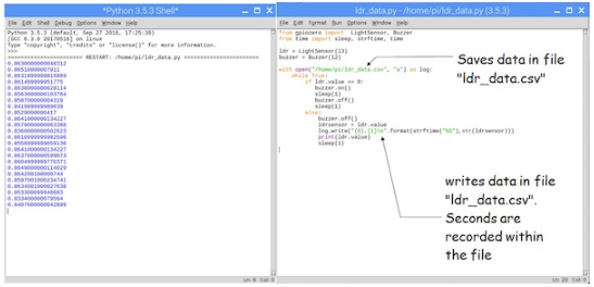
After typing the code, you can run the monitoring-detection application by pressing Ctrl S and then F5 on the keyboard. The data will be displayed on the screen as shown in Figure 8.
Figure 8. The Python ldr_data.py code running on the Pi Zero W.
Placing your hand or an object over the collimator will sound the alarm from the piezo buzzer. The loudness of the alarm can be adjusted using the 10KΩ trimmer or linear potentiometer (R2) component.
And that’s it! You have successfully built a functional simple object detector using PC techniques. You can see the stored data by going to the home/pi directory and opening the ldr_data.py file using LibreOffice or Notepad.
As an exploratory activity, see if you can plot your data using the Excel software package. Also, take this tutorial and build on it by trying other sensor devices like a thermistor and observe the data on the screen.