Learn how to control a DC motor connected to a Raspberry Pi Zero WH with EduBlocks, a Blockly-based language.
The Raspberry Pi Zero WH can be used in a variety of coding and electronics projects. Besides being able to print graphics on a screen or create animated games, the Raspberry Pi Zero WH can be used to perform automation tasks. One such task is the operation of an electric DC motor.
In this tutorial, you will learn how to wire a small DC electric motor to a Raspberry Pi Zero WH and how to control the motor using EduBlocks. You’ll also learn how to build a mini programmable automation controller (PAC).
Required Hardware
DC Motor Driver Circuit
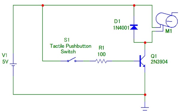
To operate a DC motor, an electric switch and DC battery can be used to control the electromechanical component. Although this simple control circuit can operate a DC motor, there is a limitation — there is no ability to operate the DC motor for speed and precision motion control applications. Therefore, a transistor is used to control the DC motor. Figure 1 shows a typical transistor DC motor driver circuit.
Figure 1. A typical transistor DC motor driver circuit.
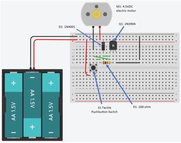
As shown in the circuit schematic diagram, the transistor DC motor driver circuit can easily be wired on a solderless breadboard. Figure 2 shows the transistor DC motor driver circuit wired on a solderless breadboard.
Figure 2. A transistor DC motor
driver circuit wired on a solderless breadboard.
Pressing the tactile pushbutton switch turns on the 2N3904 transistor. The transistor allows electrical current to flow from its collector pin through the 4.5 DC electric motor’s winding and emitter pin to ground. The motor’s shaft will rotate. Releasing the tactile switch stops the motor from rotating.
Although you can use a tactile pushbutton switch to operate the transistor DC motor driver circuit, the electronic device can be improved using an automatic software control technique.
Operating the Circuit With a Raspberry Pi Zero WH
You can improve the transistor DC motor driver circuit using a Raspberry Pi Zero WH as a mini PAC to operate the transistor DC motor driver circuit. You will program your mini PAC using EduBlocks software.
If you have not installed EduBlocks onto the Pi Zero WH, follow the installation instructions from the getting started tutorial.
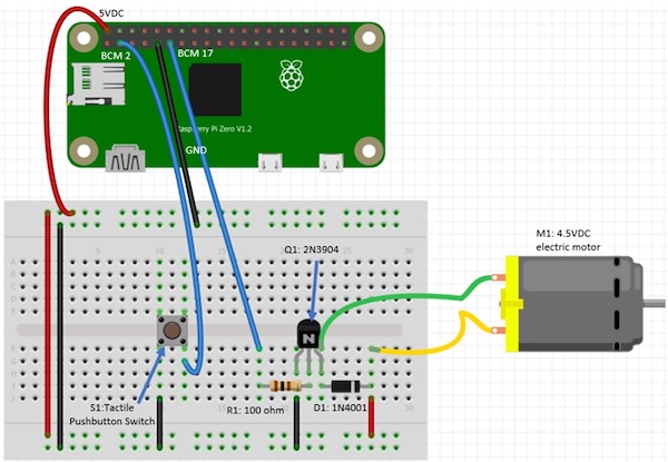
Once EduBlocks is installed, wire your transistor DC motor driver circuit to the Raspberry Pi using the wiring diagram shown in Figure 3.
Figure 3. The electrical wiring diagram
for the mini PAC DC motor controller.
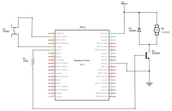
The orientation of the 2N3904 NPN transistor and the 1N4001 diode is important. You will need to follow the placement of the components onto the solderless breadboard as close as possible. Not following the electrical wiring diagram may cause the transistor driver circuit to not operate properly. As an additional reference, the electronic circuit schematic diagram is provided in Figure 4.
Figure 4. Circuit schematic diagram
for the Raspberry Pi Zero WH based mini PAC DC motor controller.
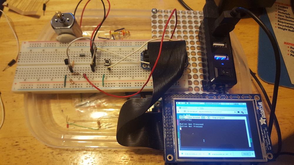
Here is my final circuit build of the mini PAC-Raspberry Pi Zero WH based DC motor controller.
Figure 5. The final build of
the mini PAC-Raspberry Pi Zero WH based DC motor controller.
I added a thin film transistor (TFT) LCD touch screen to act as a human-machine interface (HMI) to program various operating modes for the electric DC motor. These operating mode functions are also programmed using the EduBlocks software. To add something similar, check out How to Set up Touchscreen Rotation for Raspberry Pi Projects.
Note that the TFT LCD touch screen is optional. With the DC motor wired to the Raspberry Pi, you are now ready to code the EduBlocks control software.
DC Motor Control EduBlocks Code
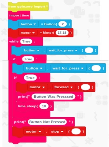
You will use the following EduBlocks code to operate the electric DC motor wired to the Pi Zero WH SBC. The EduBlocks code allows the electric DC motor to operate for 10 seconds after the tactile pushbutton switch has been pressed and released.
The smart timer feature provides a programmable jog function for operating the electric DC motor. You can easily change to the time of the smart timer feature by entering a new time. sleep () value.
Also, two tactile pushbutton event messages of Button was Pressed and Button not Pressed will be displayed on the touch screen or HDMI monitor.
Figure 6. The EduBlocks code to
operate the electric DC motor wired to the Pi Zero WH.
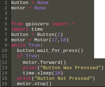
The equivalent Python-based GPIO Zero code is provided in Figure 7 as reference.
Figure 7. The equivalent Python-based
GPIO Zero code.
As a design challenge, try replacing the tactile pushbutton switch with a light sensor for hand gesture operation and control of the electric DC motor. Happy controlling!