In this tutorial, we will be connecting a 20x4 LCD screen to a Raspberry Pi using a logic converter and an I2C bus!
Nowadays, LCD screens can be found on various devices, like smartphones, televisions, monitors, and handheld devices. There are many various LCD sizes, and choosing the right size depends on your needs and functions.
In this tutorial, we will be connecting a 20x4 LCD screen to a Raspberry Pi with the help of other components including a logic converter and an I2C bus. Before diving in, collect the necessary hardware.
Required Hardware
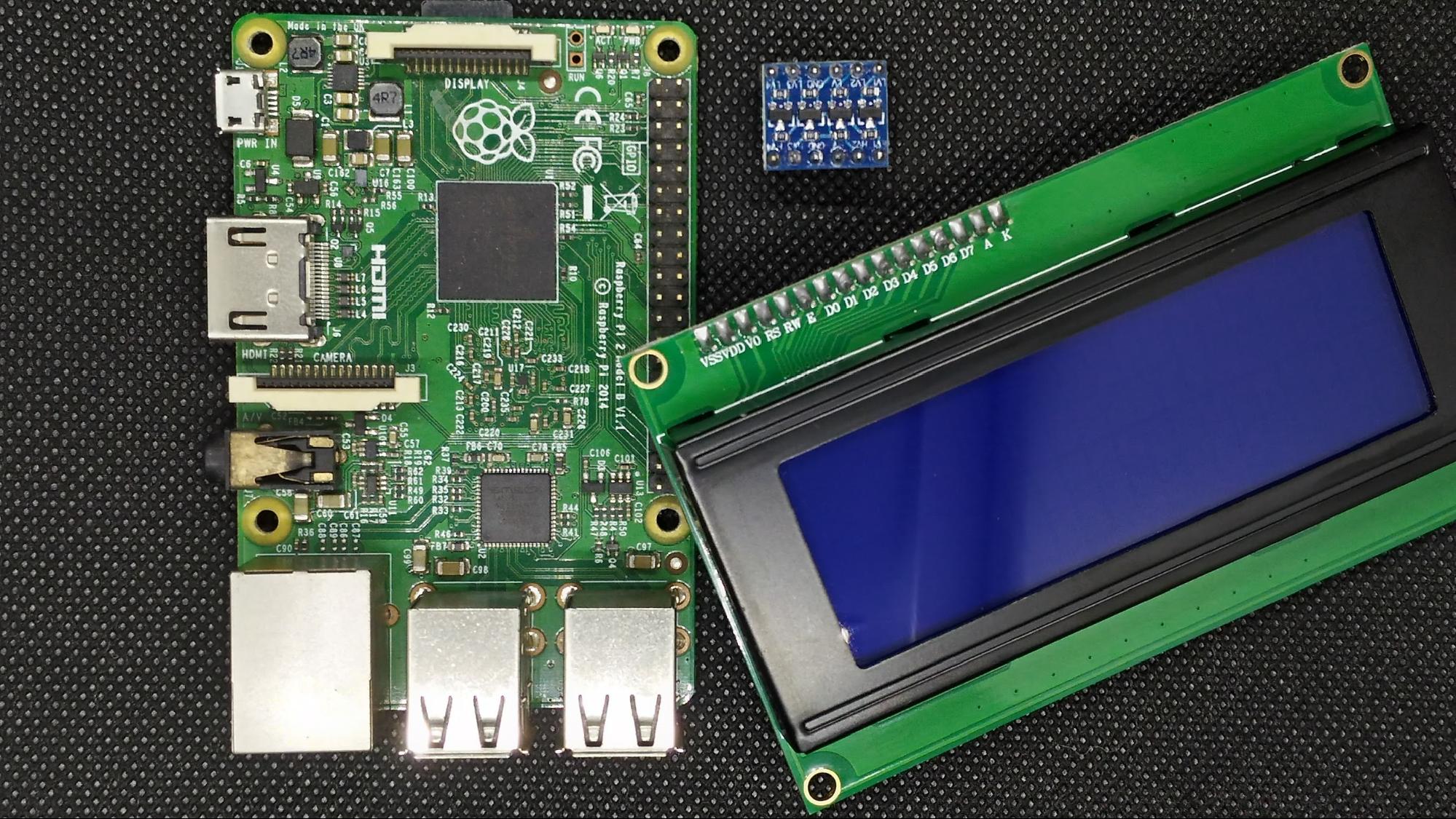
- Raspberry Pi
- 20x4 I2C LCD screen
- Breadboard
- Logic converter
- Raspberry Pi Cobbler
- Wires
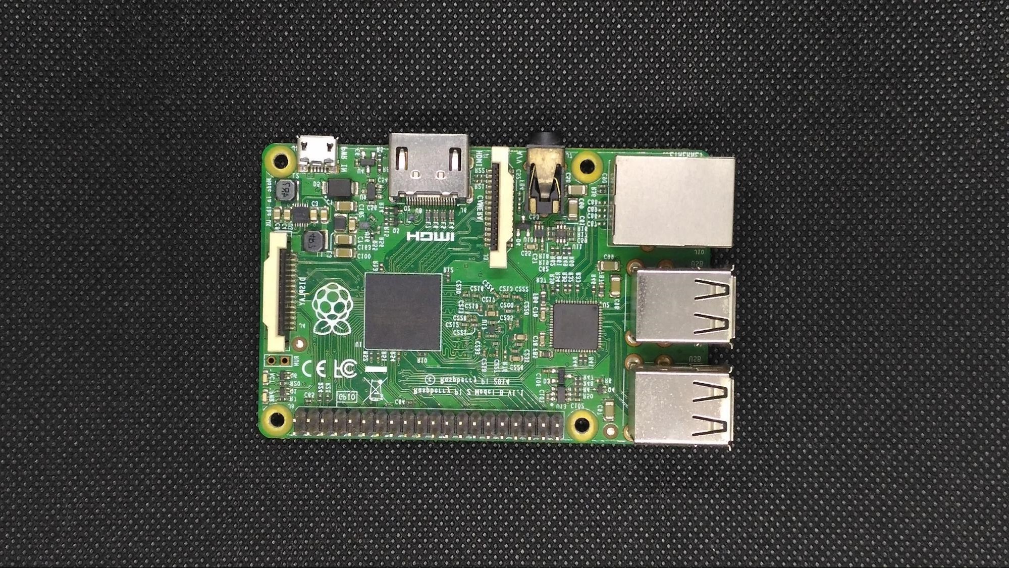
A Quick Look at the Raspberry Pi SBC
The Raspberry Pi is a single-board microcomputer designed for hobbyists and technology enthusiasts who are starting out in the world of electronics and programming. The latest Raspberry Pi version is the Raspberry Pi 4 Model B. It includes a 1.5Ghz quad-core processor, a selection of 1GB, 2GB or 4GB of RAM version, onboard Wi-Fi and Bluetooth, gigabit Ethernet, dual micro HDMI ports, USB 3.0 and USB-C power supply.
The 20x4 LCD With I2C Adapter
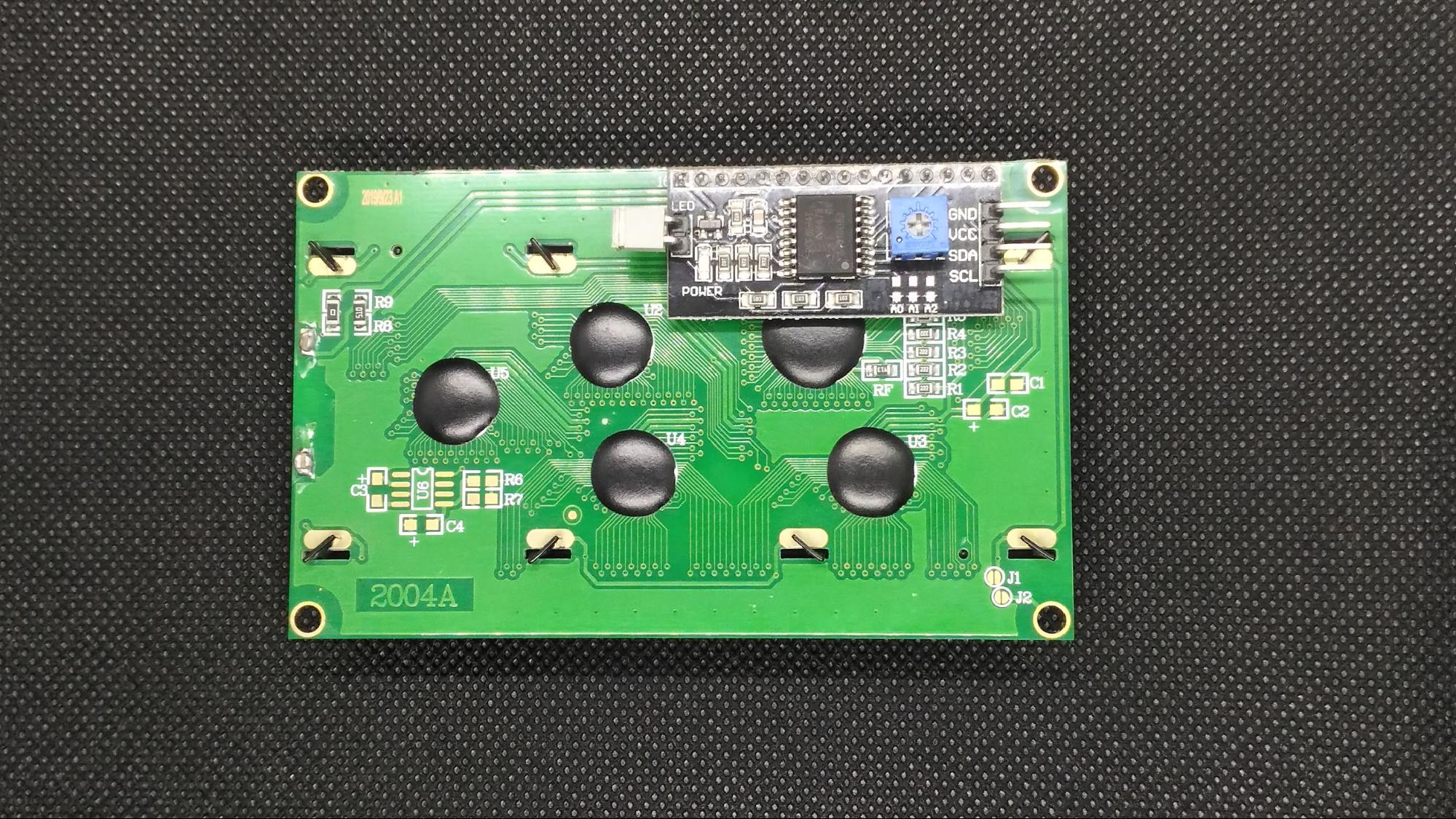
The 20x4 LCD with an I2C adapter uses the common HD44780 chipset. This LCD display also includes an I2C adapter board based on the PCF85741 I2C chip, which converts I2C serial data to parallel data for the LCD screen.
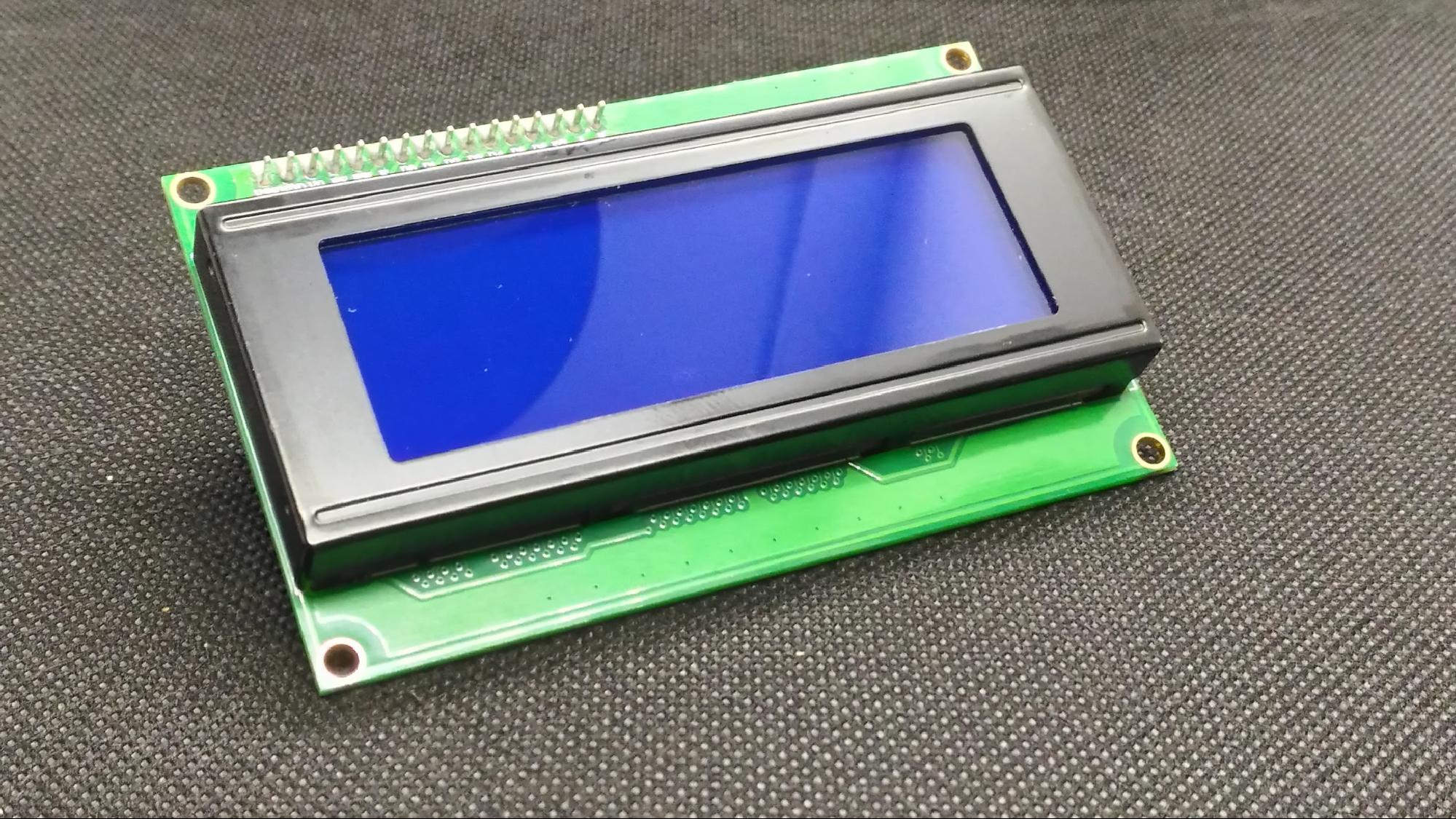
It can display four lines of 20 characters and includes an LED backlight to increase readability in low light conditions. It also has a potentiometer at the back which allows us to adjust the contrast.
LCD Features
- Working voltage: 5V DC
- I2C LCD 20x4: Displays four lines of characters with 20 characters each
- I2C Interface: Only two I/O ports are required
- Suitable for Raspberry Pi or Arduino Uno/Mega2560 development board
- LCD Display Type: Character
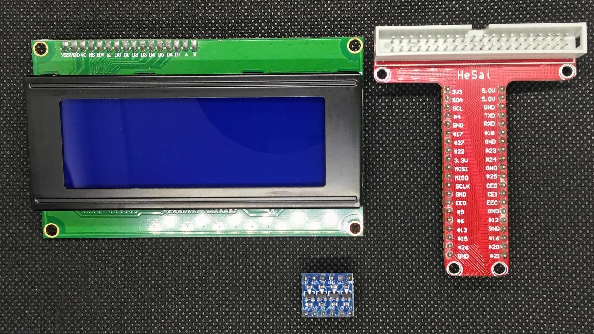
The front of the LCD screen.
The back of the LCD screen.
What is a Logic Converter?
Have you ever wondered how to connect a 3.3V I2C or SPI sensor to a 5V GPIO pin? Or a 5V device/sensor that needs to be compatible with a 3.3V GPIO Raspberry Pi pin? To solve this problem, you need a device that can shift 3.3V up to 5V or 5V down to 3.3V. This is called logic level converter shifting.
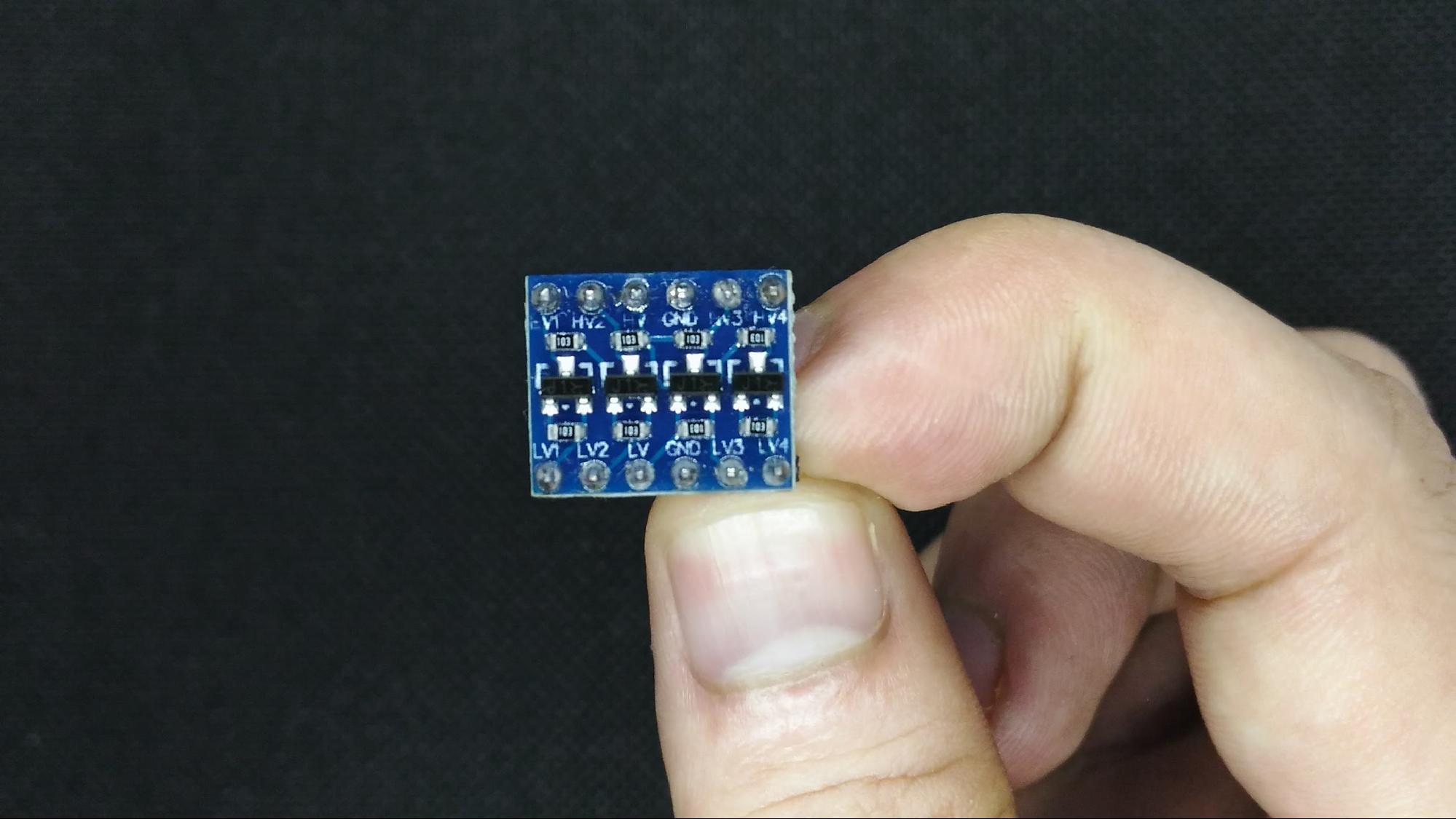
Logic converters are bi-directional. They have the ability to convert four pins on the high side to four pins on the low side with two inputs and two outputs provided for each side.
Bi-directional logic converter.
Raspberry Pi Cobbler
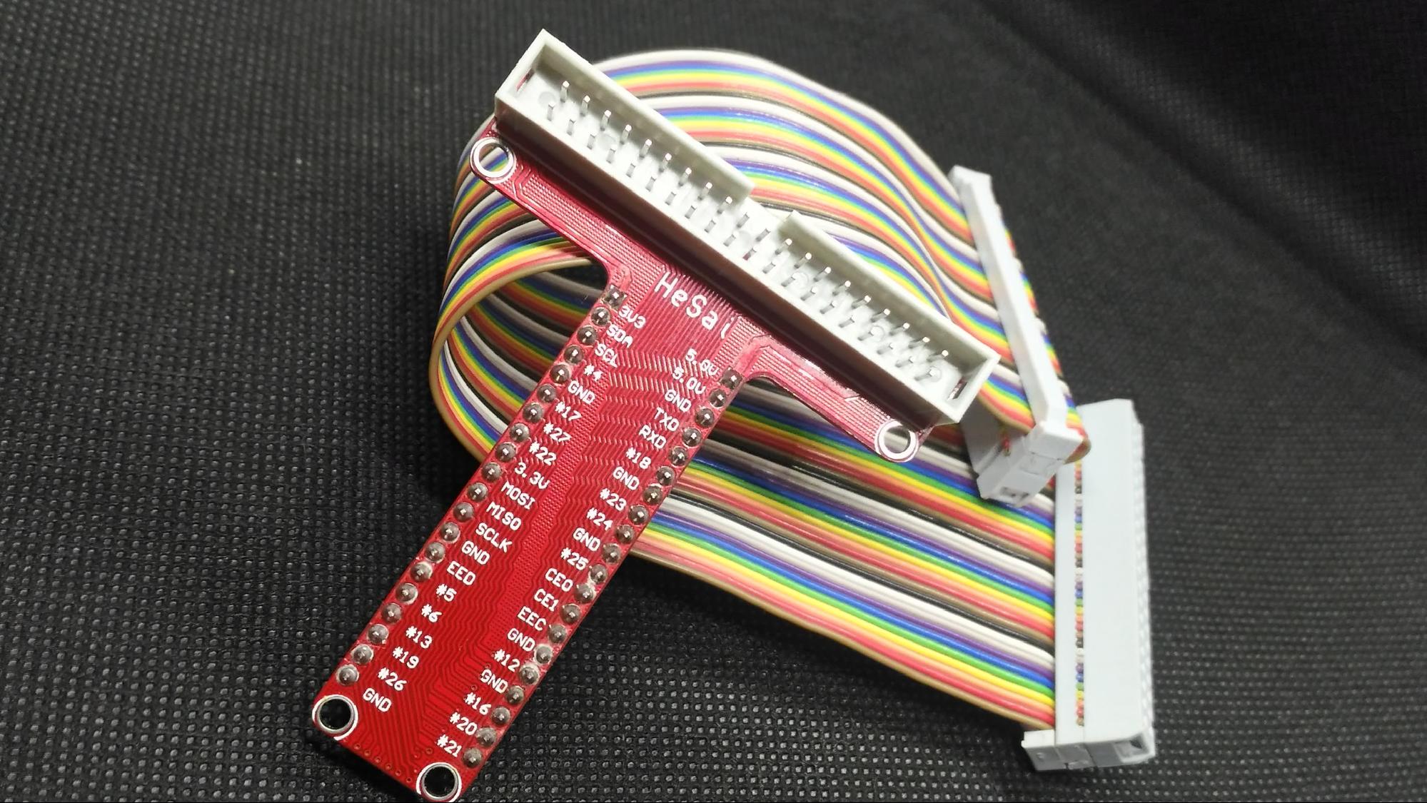
Prototyping with Raspberry Pi is made even easier with the help of Raspberry Pi Cobbler. The Cobber helps reduce time and prevent short circuits with a breadboard-friendly interface. All you have to do is to connect the other end to your Raspberry Pi and you can access the Raspberry Pi GPIO, which includes its I2C and SPI pins.
Assembling the Hardware
I am using a Raspberry Pi 2B, which the Cobbler is compatible with. If you are using different versions of Raspberry Pi, chances are the Cobbler may also have different pins. Just look for compatible Raspberry Pi versions for your cobbler of choice.
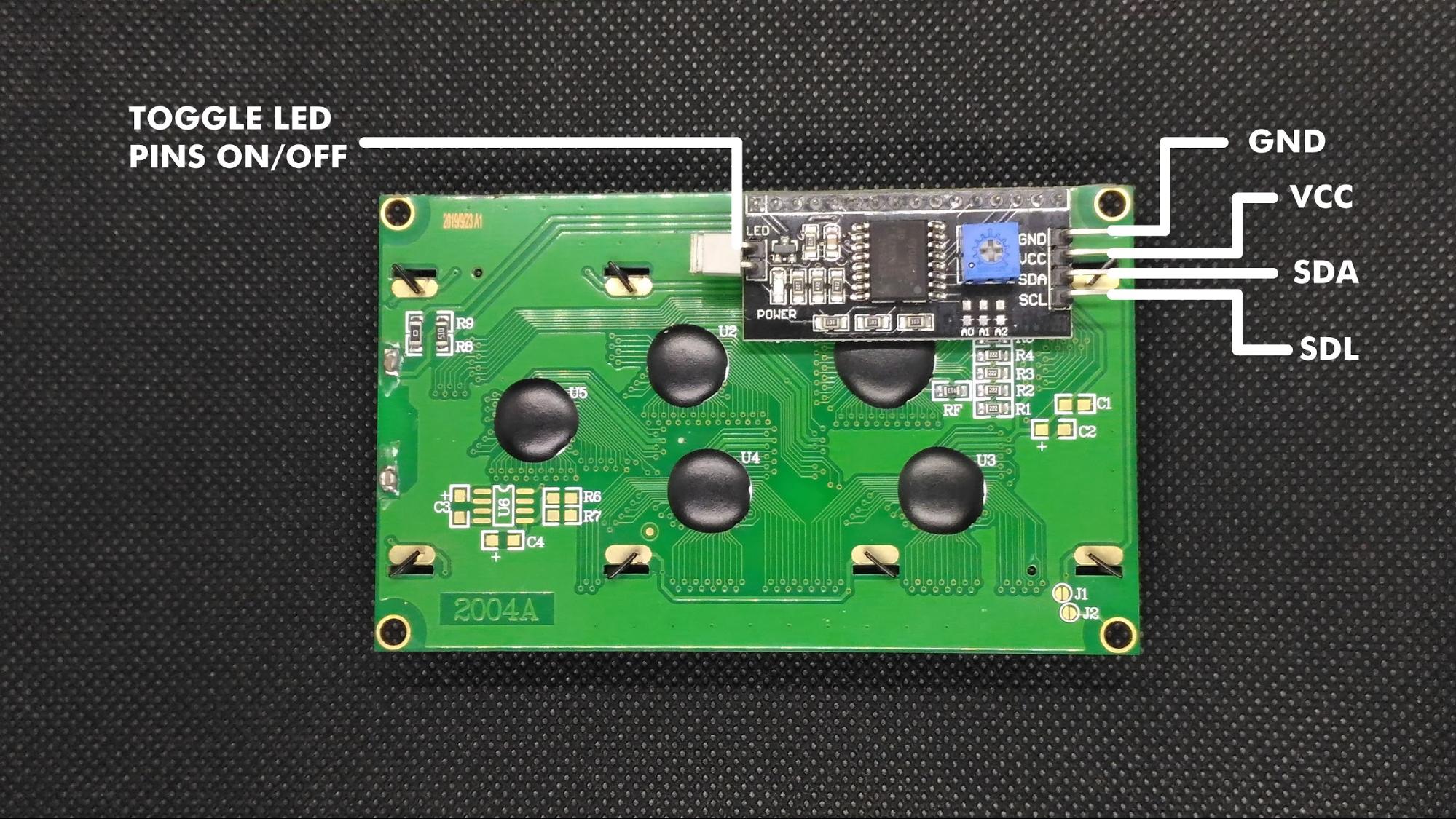
We first identify the underlying pins of our 20x4 LCD I2C display. We will use the GND pin, VCC pin, SDA, and SCL pins. The SDA and SCL pins are data and clock lines, used to synchronize all data transfer over the I2C bus.
The LED’s backlight also can be turned off if you remove the jumpers at the back of the module. It depends on whether you are working in a low or high light environment.
Assembling the Hardware
I am using a Raspberry Pi 2B, which the Cobbler is compatible with. If you are using different versions of Raspberry Pi, chances are the Cobbler may also have different pins. Just look for compatible Raspberry Pi versions for your cobbler of choice.
We first identify the underlying pins of our 20x4 LCD I2C display. We will use the GND pin, VCC pin, SDA, and SCL pins. The SDA and SCL pins are data and clock lines, used to synchronize all data transfer over the I2C bus.
The LED’s backlight also can be turned off if you remove the jumpers at the back of the module. It depends on whether you are working in a low or high light environment.
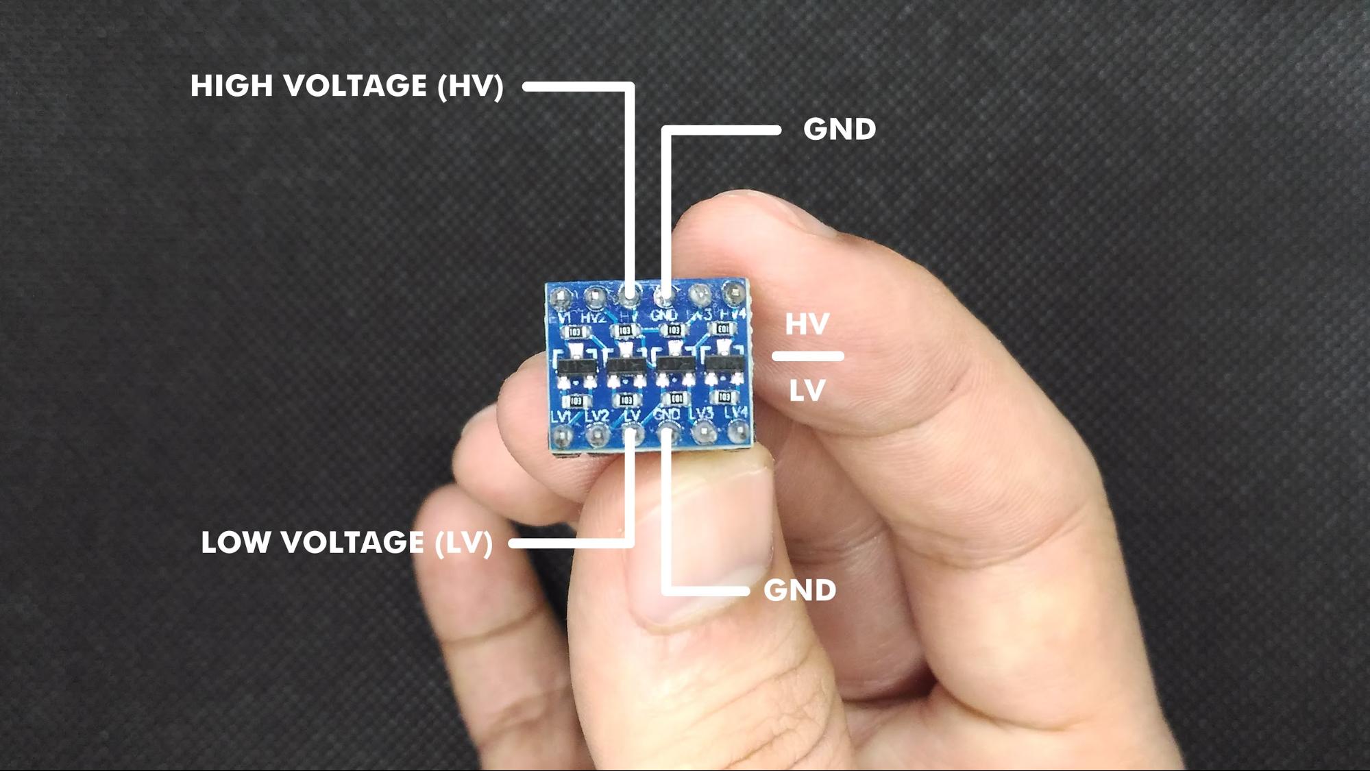
After identifying the pins of the 20x4 LCD I2C display, we can proceed to the pins of the logic level converter.
It’s okay if you are using a different model of logic level converter/shifter, as long as you identify the HV (high voltage), LV (low voltage), high side, low side, and the GND pins.
Raspberry Pi’s GPIO max voltage is 3.3V (SDA and SCL supplies 3.3V). For it to work with a 20x4 LCD I2C screen, we need 3.3V to shift to 5V. That’s where the logic converter comes in.
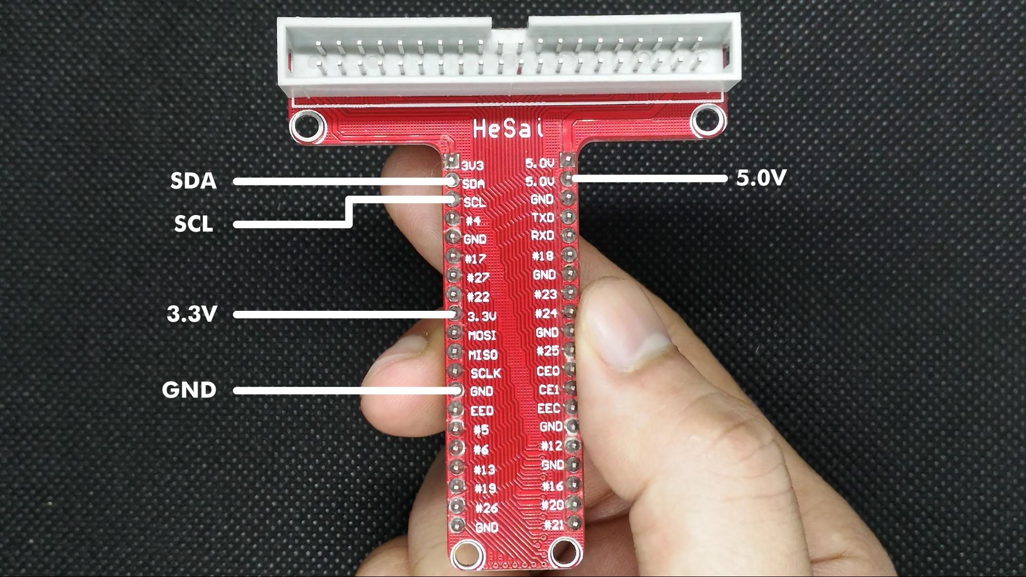
Next, we must identify the Cobbler pins we are using.
For the 20x4 LCD to work, we need the data lines — namely, SDA (serial data) and SCL (serial clock). We will also be using the 3.3V and 5V pins from the Raspberry Pi GPIO.
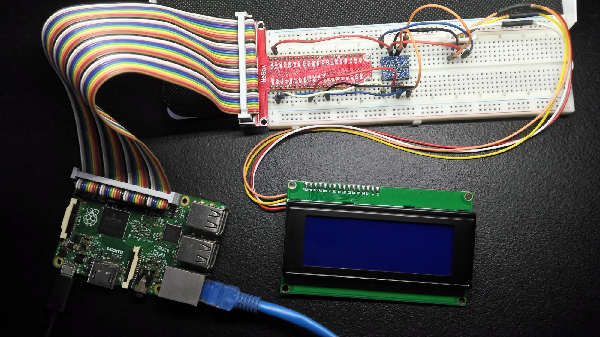
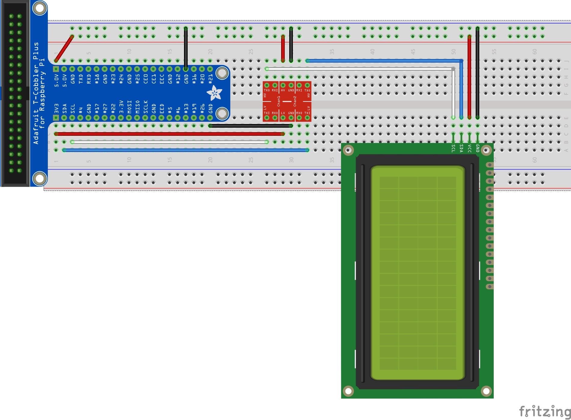
Here is our circuit diagram:
Software
Before we can control the LCD via Raspberry Pi, we need two I2C tools, which we install:
sudo apt-get install python-smbus i2c-tools
After the installation of these tools, we can activate I2C via the Raspberry Pi configuration menu:
sudo raspi-config
Under Interfacing Options, we activate I2C. After that, we need to edit a file called Modules under the Directory/Etc:
sudo nano /etc/modules
We add two lines of code to the end of the file:
i2c-bcm2708
i2c-dev
To save all the changes, we must reboot the system by issuing:
sudo reboot
If you have already followed the circuit diagram, you can now test to see if the LCD was detected by the Raspberry Pi:
sudo i2cdetect -y 1
What is I2Cdetect?
I2Cdetect is a tool/program used to scan an I2C bus for devices. It shows a table with the list of detected devices on the specified bus. It also indicates the number or name of the I2C bus that you are using.
If you have already issued the I2Cdetect command, your output should look like this:
pi@raspberrypi ~ $ sudo i2cdetect -y 1
        0   1   2   3   4   5   6   7   8   9   a   b   c  d  e  f
00:                --  --  --  --  --  --  --  --  --  --  --  --  --
10:  --  --  --  --  --  --  --  --  --  --  --  --  --  --  --  --
20:  -- -- -- -- -- -- -- 27 -- -- -- -- -- -- -- -- -- -- -- -
30:  -- -- -- -- -- -- -- -- -- -- -- -- -- -- -- -- -- -- -- --
40:  -- -- -- -- -- -- -- -- -- -- -- -- -- -- -- -- -- -- -- --
50:  -- -- -- -- -- -- -- -- -- -- -- -- -- -- -- -- -- -- -- --
60:  -- -- -- -- -- -- -- -- -- -- -- -- -- -- -- -- -- -- -- --
70:  -- -- -- -- -- -- -- -- -- -- -- -- -- -- -- -- -- -- -- --
You must see the number 27, which indicates that the LCD was detected.
LCD Scripts
To make the LCD work, we need two scripts:
- I2C_lib.py - the I2C library that contains classes and methods
- Lcddriver.py - the LCD driver thats contains hex addresses for each operation
You can download the two scripts from the zip file at the end of the article.
Now we create the main script that includes the text we want to display on the LCD:
import lcddriver
from time import *

lcd = lcddriver.lcd()
lcd.lcd_clear()

lcd.lcd_display_string("Hello", 1)
lcd.lcd_display_string("from", 2)
lcd.lcd_display_string("the", 3)
lcd.lcd_display_string("20x4 i2c lcd", 4)
The first parameter of the method lcd_display_string is for the text and the second is for the row. You can now modify this code based on your project.