Need help waking up? Use a Raspberry Pi Zero and a DS3231 RTC Module to create an alarm clock!
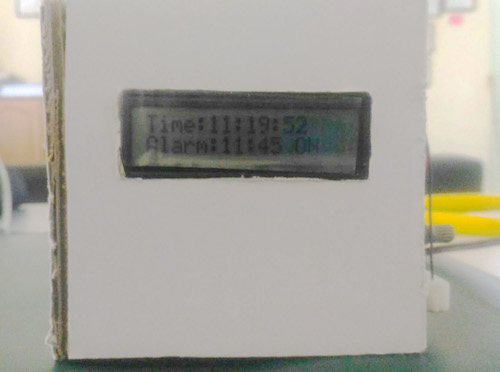
In this tutorial, we are going to create a digital alarm clock based on a Raspberry Pi Zero and the DS3231 RTC Module. The digital clock will feature an alarm function and display for easy use. The 16x2 character LCD is used to display real-time, alarm time, and alarm status (ON/OFF).
The build is divided into three different parts:
- Connecting our hardware to the Raspberry Pi Zero.
- Creating the program for the digital clock with alarm features.
- Creating the casing of the clock.
Required Hardware
- RTC DS3231 Module
- Raspberry Pi Zero W
- 16x2 Character LCD Module
- Buzzer
- 5 x Push Button Pins
- Some resistors and capacitors
Connecting the Pi Zero to the DS3231 and LCD
For the first part, we are going to start by connecting the Raspberry Pi Zero W with a RTC module and the 16 x 2 Character LCD Display. This is the foundation of the whole project.
Circuit Diagram
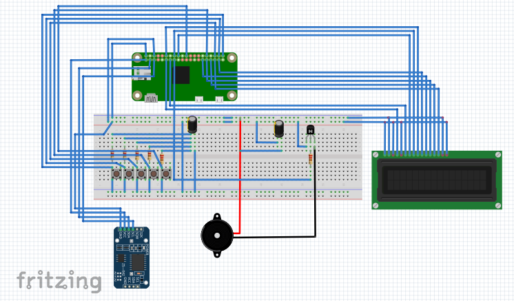
The project’s full circuit diagram can be found below. To further understand how everything works, we will deconstruct each connection and discuss how each one functions in the circuit.
The Pi Zero alarm clock circuit diagram.
First, we connect our 16x2 LCD module to the Pi Zero. The table below shows these connections to simplify this process.
Before you start making the connections, check the model of your LCD Display — in this project we are using the LCM-S01602DSR/B. Also, make sure you are familiar with the pinout of your Pi Zero.
Raspberry Pi Zero | LCD Connection |
|---|
GND | GND |
+5V | VCC |
GND | VEE |
GPIO17 | RS |
GND | R/W |
GPIO27 | EN |
GPIO24 | D0 |
GPIO23 | D1 |
GPIO18 | D2 |
GPIO26 | D3 |
GPIO5 | D4 |
GPIO6 | D5 |
GPIO13 | D6 |
GPIO19 | D7 |
Next, we connect the RTC module. Connect VCC on the breakout board to the 3.3V pin of the Pi Zero. The GND pin on the breakout board goes to the GND pin of the Pi Zero. The SDA and SCL pins on the breakout board to the SDA and SCL pin of the Pi. Refer to the article on how to set up your RTC module with a Raspberry Pi. It is important to pay attention to the details discussed in the previous article to get accurate time from the DS3231.
After connecting the LCD and the RTC to the Pi Zero, we can connect the five buttons to the Pi Zero. The table below shows the respective functions of each button.
Raspberry Pi Zero | Push Button | Function |
|---|
GPIO21 | 1 | Hour Increase |
GPIO20 | 2 | Hour Decrease |
GPIO16 | 3 | Minute Increase |
GPIO12 | 4 | Minute Decrease |
GPIO25 | 5 | Alarm ON/OFF |
With the hardware connections complete, we can write the code to run our desk clock.
Programming the Alarm Clock
The program for this project is pretty straight forward. All we need to display is the time.
Note: It is important to install/download the libraries needed for this project ahead of time.
Create an empty Python file and paste the code from the zip file found at the end of the article.
With the code ready, open the terminal. Run the code, and everything should work as programmed. If no errors come up, Hurray! The hardware for the digital desk clock with alarm features is complete.
Digital Desk Clock Design
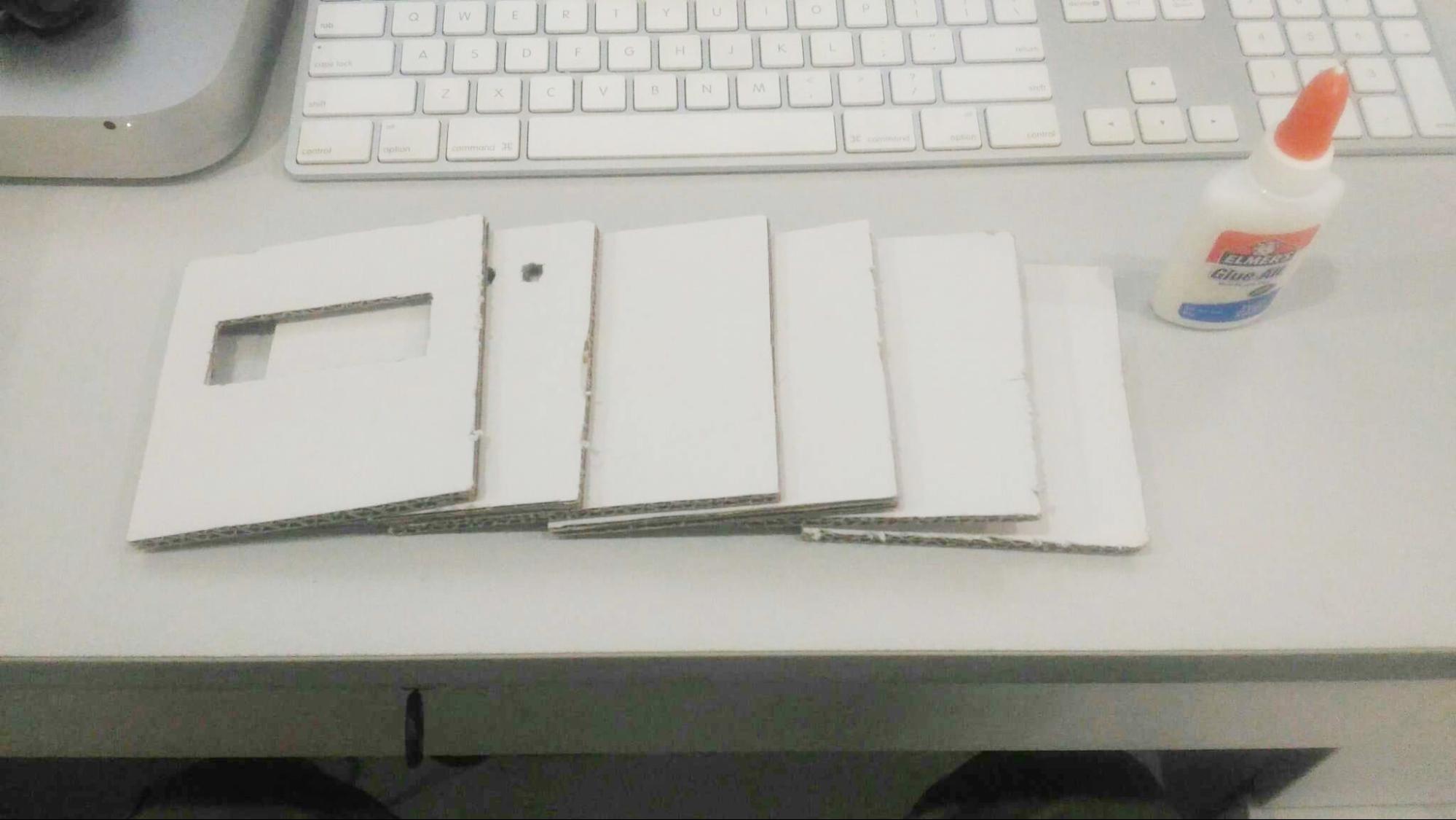
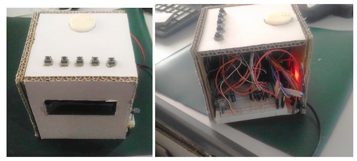
With the clock built and programmed, it's time to create a case for it. I decided to build a simple casing out of cardboard that I had around.
Materials
- 4 pcs - 4 x 4 " Cardboard
- 2 pcs - 4 x 4.5 " Cardboard
- Glue
- Cutter
- Jumper Wires
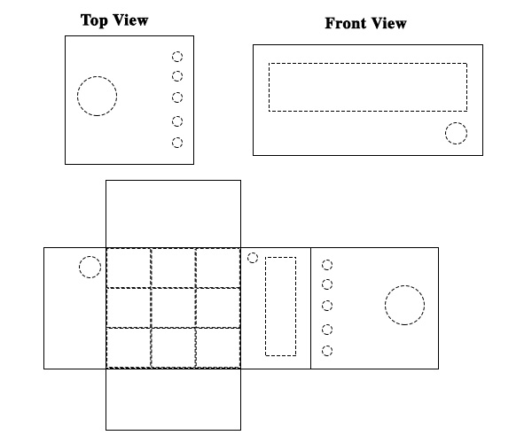
The layout for the alarm clock's casing.
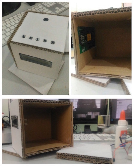
Using any kind of glue, stick together each piece to form the shape of a box.
Assembling the parts of the casing.
Once the glue on the casing is completely dry, we can connect the wires just as we did on the breadboard. Once done, It should look something like this:
Insert the hardware into the casing.
When everything is set, you now have your very own digital desk clock with alarm. Hope you enjoy this project!
The build is done and the alarm is set!