In this tutorial, you are going to learn about how to control DC motor with Raspberry Pi.
In this tutorial, you are going to learn about how to control DC motor with Raspberry Pi. We will use L293D motor driver IC to control the motors. L293D is a powerful IC that can control direction and speed of two DC motors running at 4.5 to 36V. It can also control stepper motor.
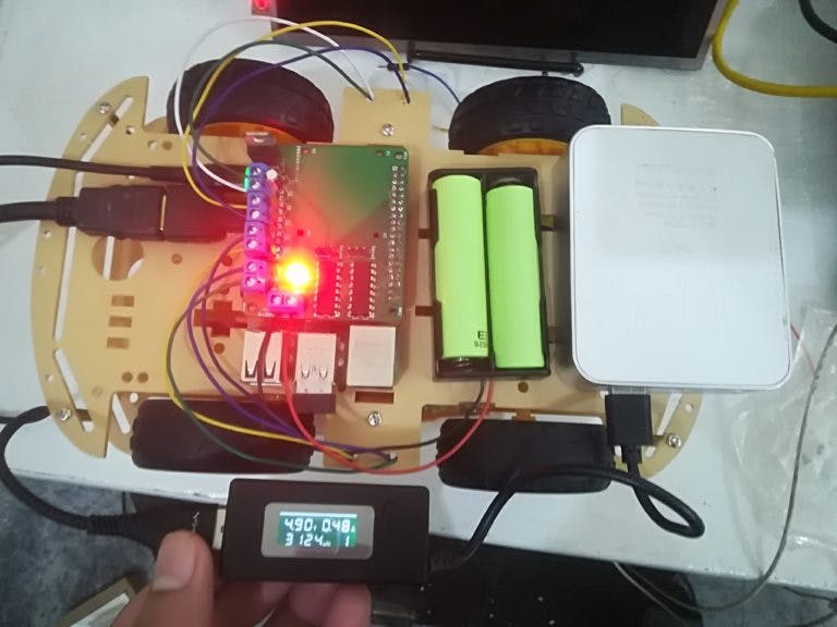
After making it on the breadboard, we will make a PCB which will include 2 L293D’s and will be able to control 4 DC motors. You can also control 2 servos with it and there is space to add pan tilt bracket to it. The PCB can control Steppers as well in place of DC motors.
L293D Motor Driver IC
L293D motor driver IC is also known as H-bridge IC. It consists of two H-bridge circuits, one for controlling each motor. The use of H-bridge in this IC is to change the polarity of the output so that DC motors can be controlled in both directions.
Pin out
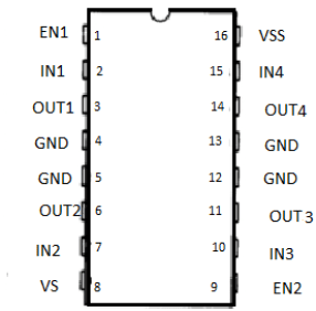
The pin out of the L293D IC is shown below.
- EN1 and EN2 are the enable pins. Motors will only move if these pins are High
- Vs is the input voltage for motor pin.The voltage given at this pin will be applied to the motors.
- Vss is the input power pin of IC. This pin will power the IC.
- IN1, IN2 and IN3, IN4 are the input pins. These pins will take input from the Raspberry Pi and according to that motors will move.
- OUT1, OUT2 and OUT3, OUT4 are the output pins. The motors will be connected there.
- GND pins are for device ground and heat sink.
Required Components
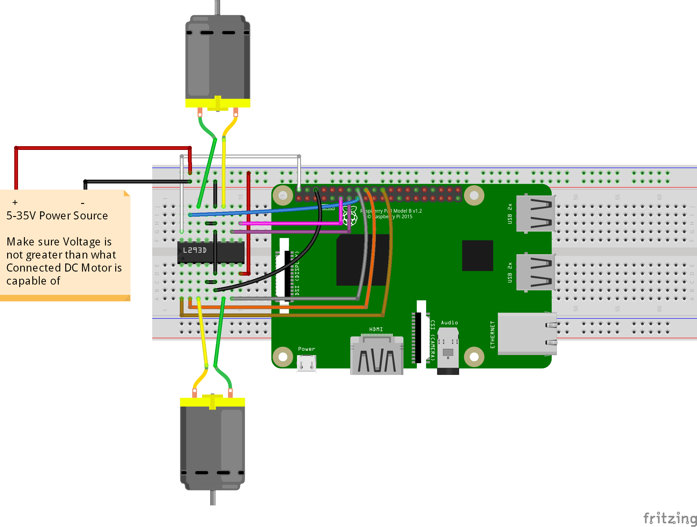
Circuit Diagram for Raspberry Pi DC Motor Control
Code for Raspberry Pi DC Motor Control
import RPi.GPIO as GPIO
from time import sleep

GPIO.setmode(GPIO.BCM)
GPIO.setwarnings(False)

Motor1 = {'EN': 25, 'input1': 24, 'input2': 23}
Motor2 = {'EN': 17, 'input1': 27, 'input2': 22}

for x in Motor1:
    GPIO.setup(Motor1[x], GPIO.OUT)
    GPIO.setup(Motor2[x], GPIO.OUT)

EN1 = GPIO.PWM(Motor1['EN'], 100)
EN2 = GPIO.PWM(Motor2['EN'], 100)

EN1.start(0)
EN2.start(0)

while True:
    for x in range(40, 100):
        print ("FORWARD MOTION")
        EN1.ChangeDutyCycle(x)
        EN2.ChangeDutyCycle(x)

        GPIO.output(Motor1['input1'], GPIO.HIGH)
        GPIO.output(Motor1['input2'], GPIO.LOW)

        GPIO.output(Motor2['input1'], GPIO.HIGH)
        GPIO.output(Motor2['input2'], GPIO.LOW)

        sleep(0.1)

    print ("STOP")
    EN1.ChangeDutyCycle(0)
    EN2.ChangeDutyCycle(0)

    sleep(5)

    for x in range(40, 100):
        print ("BACKWARD MOTION")
        EN1.ChangeDutyCycle(x)
        EN2.ChangeDutyCycle(x)

        GPIO.output(Motor1['input1'], GPIO.LOW)
        GPIO.output(Motor1['input2'], GPIO.HIGH)

        GPIO.output(Motor2['input1'], GPIO.LOW)
        GPIO.output(Motor2['input2'], GPIO.HIGH)

        sleep(0.1)

    print ("STOP")
    EN1.ChangeDutyCycle(0)
    EN2.ChangeDutyCycle(0)

    sleep(5)

GPIO.cleanup()
Video
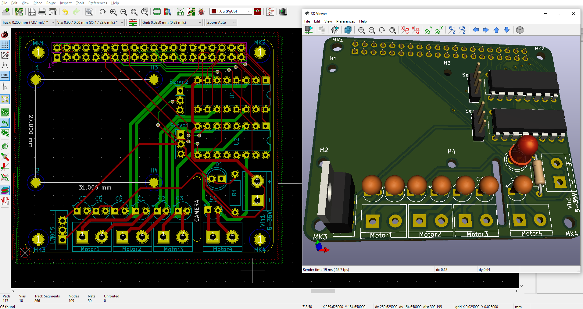
PCB Design
After making sure everything works fine on the breadboard, I have designed the PCB on KiCad.
Following is a link to the project folder of this project.
After designing the PCB’s, I generated the Gerber file needed for manufacturing of PCB.
You can download the Gerber file through following link
Required Components for PCB
Ordering the PCB’s
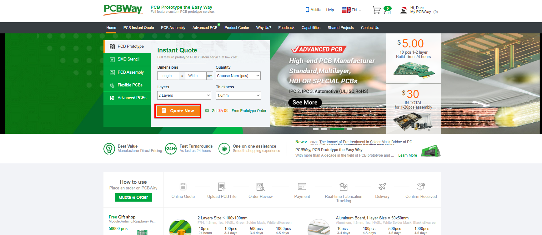
Now we have got the PCB design and it’s time to order the PCB’s. For that, you just have to go to PCBWay.com, and click on “QUOTE NOW” button.
PCBWay are also sponsor of this project. PCBWay is a China Shenzhen-based PCB manufacturer and PCB assembler. You can instantly get the quotation of your PCB and PCBA, you can also check the order fabrication and processing status online in your account panel with PCBWay. You can order a minimum of 5 PCBs for just $5.
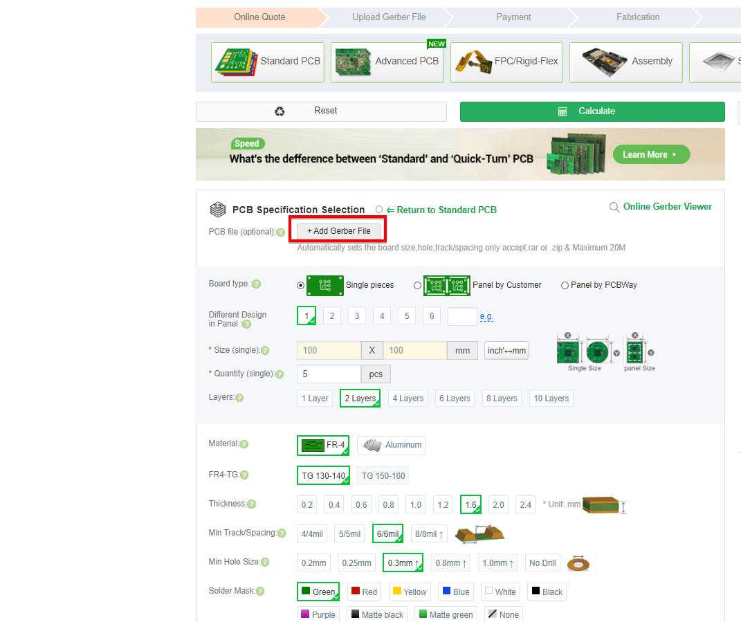
Next Click on Quick-order PCB.
To get the PCB manufactured, upload the gerber file given in the PCB Design Step.
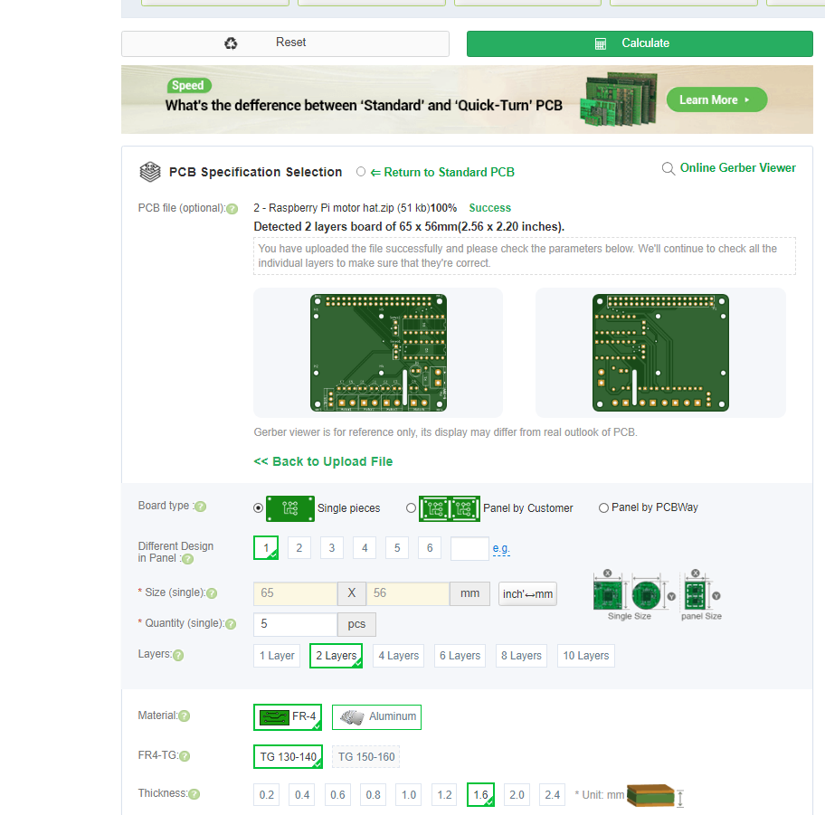
Then check the files and click on add to cart.
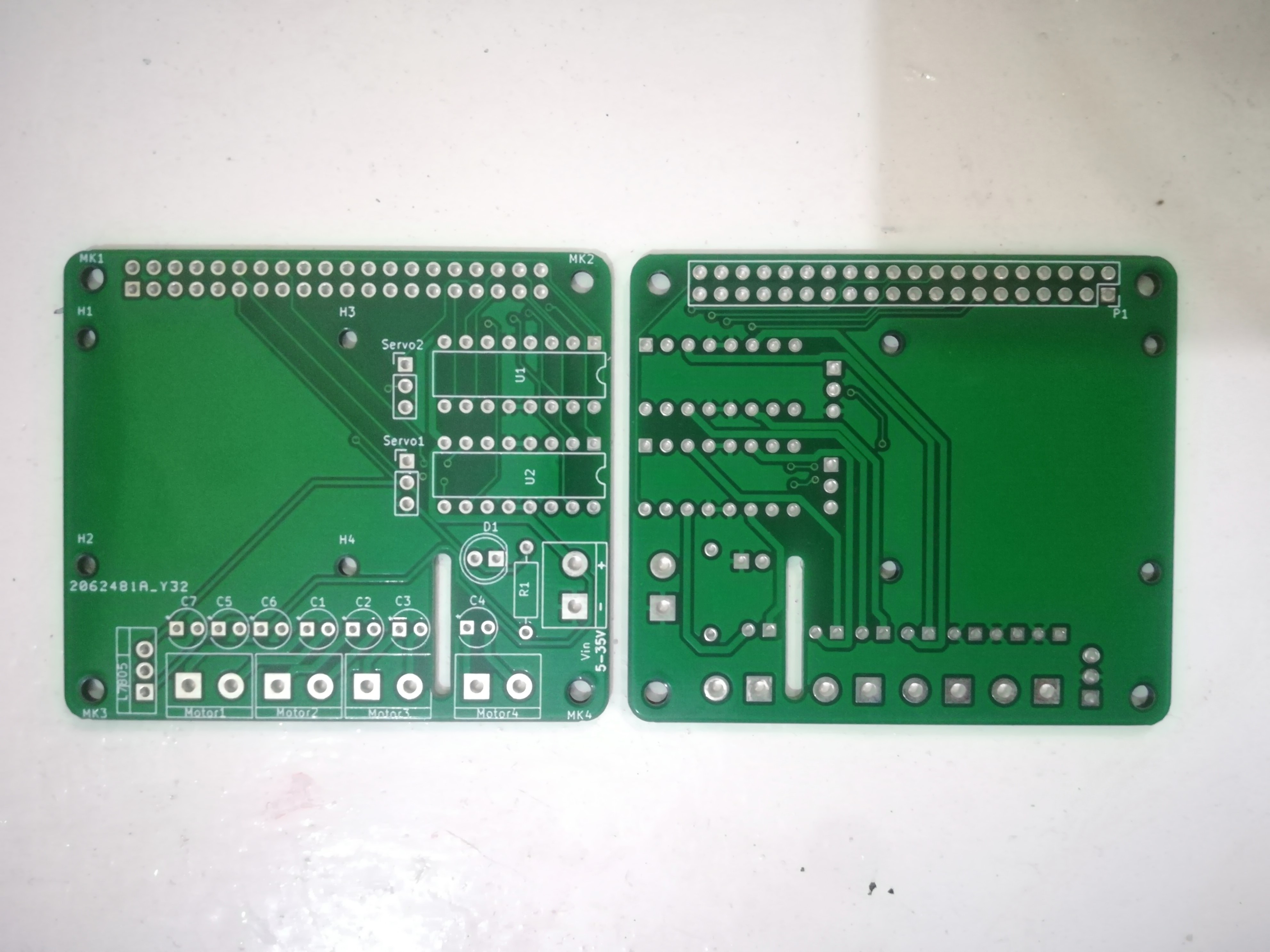
My PCBs took 2 days to get manufactured and arrived within a week using DHL delivery option. PCBs were well packed and the quality was really good.
Code
import RPi.GPIO as GPIO
from time import sleep

GPIO.setmode(GPIO.BCM)
GPIO.setwarnings(False)

Motor1 = {'EN': 21, 'input1': 20, 'input2': 16}
Motor2 = {'EN': 6, 'input1': 19, 'input2': 26}
Motor3 = {'EN': 25, 'input1': 23, 'input2': 24}
Motor4 = {'EN': 17, 'input1': 27, 'input2': 22}

for x in Motor1:
    GPIO.setup(Motor1[x], GPIO.OUT)
    GPIO.setup(Motor2[x], GPIO.OUT)
    GPIO.setup(Motor3[x], GPIO.OUT)
    GPIO.setup(Motor4[x], GPIO.OUT)

EN1 = GPIO.PWM(Motor1['EN'], 100)
EN2 = GPIO.PWM(Motor2['EN'], 100)
EN3 = GPIO.PWM(Motor3['EN'], 100)
EN4 = GPIO.PWM(Motor4['EN'], 100)

EN1.start(0)
EN2.start(0)
EN3.start(0)
EN4.start(0)

while True:
    for x in range(40, 100):
        print ("FORWARD MOTION")
        EN1.ChangeDutyCycle(x)
        EN2.ChangeDutyCycle(x)
        EN3.ChangeDutyCycle(x)
        EN4.ChangeDutyCycle(x)

        GPIO.output(Motor1['input1'], GPIO.HIGH)
        GPIO.output(Motor1['input2'], GPIO.LOW)

        GPIO.output(Motor2['input1'], GPIO.HIGH)
        GPIO.output(Motor2['input2'], GPIO.LOW)

        GPIO.output(Motor3['input1'], GPIO.HIGH)
        GPIO.output(Motor3['input2'], GPIO.LOW)

        GPIO.output(Motor4['input1'], GPIO.HIGH)
        GPIO.output(Motor4['input2'], GPIO.LOW)
        sleep(0.1)

    print ("STOP")
    EN1.ChangeDutyCycle(0)
    EN2.ChangeDutyCycle(0)
    EN3.ChangeDutyCycle(0)
    EN4.ChangeDutyCycle(0)

    sleep(5)

    for x in range(40, 100):
        print ("BACKWARD MOTION")
        EN1.ChangeDutyCycle(x)
        EN2.ChangeDutyCycle(x)
        EN3.ChangeDutyCycle(x)
        EN4.ChangeDutyCycle(x)

        GPIO.output(Motor1['input1'], GPIO.LOW)
        GPIO.output(Motor1['input2'], GPIO.HIGH)

        GPIO.output(Motor2['input1'], GPIO.LOW)
        GPIO.output(Motor2['input2'], GPIO.HIGH)

        GPIO.output(Motor3['input1'], GPIO.LOW)
        GPIO.output(Motor3['input2'], GPIO.HIGH)

        GPIO.output(Motor4['input1'], GPIO.LOW)
        GPIO.output(Motor4['input2'], GPIO.HIGH)
        sleep(0.1)

    print ("STOP")
    EN1.ChangeDutyCycle(0)
    EN2.ChangeDutyCycle(0)
    EN3.ChangeDutyCycle(0)
    EN4.ChangeDutyCycle(0)

    sleep(5)

GPIO.cleanup()
Video
If you have any questions, feel free to ask in comment section.