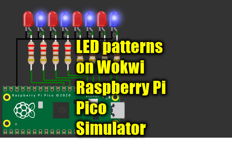
Raspberry Pi Pico simulator from wokwi. The Raspberry Pi Pico emulator can run on browsers. No downloads needed!
Learn to Drive 8 LEDs with 1 line Code on Raspberry Pi Pico. You can change the code and play with the Raspberry Pi Pico simulator.
Introduction to Raspberry Pi Pico
Raspberry Pi Pico is a little, fast, and versatile board built using RP2040, a brand new microcontroller chip devised by Raspberry Pi in the UK. You can have a look at the datasheet of Pico. You will find the getting started guide on Pi Pico here.
- Below are the features of the RP2040 microcontroller:
- Dual ARM Cortex-M0+ @ 133MHz
- 264kB on-chip SRAM in six independent banks
- Support for up to 16MB of off-chip Flash memory via dedicated QSPI bus
- DMA controller
- Fully-connected AHB crossbar
- Interpolator and integer divider peripherals
- On-chip programmable LDO to generate core voltage
- 2 on-chip PLLs to generate USB and core clocks
- 30 GPIO pins, 4 of which can be used as analogue inputs
- Peripherals ◦ 2 UARTs ◦ 2 SPI controllers ◦ 2 I2C controllers ◦ 16 PWM channels ◦ USB 1.1 controller and PHY, with host and device support ◦ 8 PIO state machines
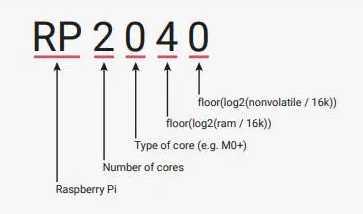
Naming convention - Hint: more versions coming soon??
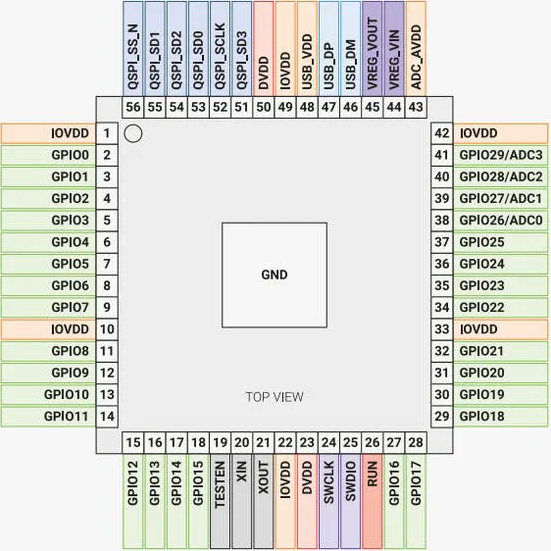
You will find the Raspberry Pi Pico pinout details of the MCU below
A word about GPIO control block in Raspberry Pi Pico
There are 26 revealed GPIO contacts on the Raspberry Pi Pico board. All the 8 bits in the port can be addressed in one instruction. I encourage you to go through the GPIO register, Atomic access topics, Singel cycle IO operation feature as well.
You can find the project here.
Raspberry Pi Pico simulation output
The sample code
/**
* Controlling the Pi Pico GPIO with direct register access (SIO registers + IO Bank 0 registers)
*
* Code example from the Raspberry Pi Pico Deep Pico - The Deep Dive course:
* https://hackaday.io/course/178733-raspberry-pi-pico-and-rp2040-the-deep-dive
*/
/* Enables the SIO function for the given pin, by writing to the relevant CTRL register.
(e.g. GPIO0_CTRL at 0x40014004) */
void enable_sio(int pin) {
uint32_t *PIN_CTRL_REG = (uint32_t*)IO_BANK0_BASE + pin * 2 + 1;
*PIN_CTRL_REG = 5; // 5 = SIO function
}
void setup() {
// Enable the SIO function for pins GP0 to GP7
for (int i = 0; i < 8; i++) {
enable_sio(i);
}
// Enable output on pins GP0 to GP7:
// sio_hw->gpio_oe points to 0xd0000020 (GPIO_OE)
sio_hw->gpio_oe = 0b11111111;
// Set initial pin pattern
// sio_hw->gpio_out points to 0xd0000010 (GPIO_OUT)
sio_hw->gpio_out = 0b10101010;
}
void loop() {
// sio_hw->gpio_togl points to 0xd000001c (GPIO_OUT_XOR)
sio_hw->gpio_togl = 0b11111111;
delay(1000);
}
The code - a deeper look
The code below sets up the SIO mode to 'Enabled' State. this is done for all the 8 PIOs (GP0 to GP7)
for (int i = 0; i < 8; i++) {
enable_sio(i);
}
Below code sets the first 8 bits (GP0-GP7) to output mode
sio_hw->gpio_oe = 0b11111111;
The below code writes the value here. This will change the Raspberry Pi Pico GP0 to GP7 to drive 1 0 1 0 1 0 1 0 on the port pins
sio_hw->gpio_out = 0b10101010;
The loop() function has only one instruction GPIO_TOGL. The GPIO toggle register will invert the bit values
void loop() {
// sio_hw->gpio_togl points to 0xd000001c (GPIO_OUT_XOR)
sio_hw->gpio_togl = 0b11111111;
delay(1000);
}
You can continue from here to create more interesting patterns. Please share your work as well. If you have any questions, feel free to jump on to the RP2040 channel on discord. You can visit to learn more about the Pi Pico online simulator and also participate in the development.
Please visit the Electrotantra YouTube channel for more videos on the Arduino and Raspberry Pi Pico simulators.