Learn how you can automate and control your light switches using Modbus, Raspberry Pi, and a NodeRed UI app.
When you are a maker and you’re in a relationship, you may recognize this situation: you build something you find ground-breaking, impressive, and easy-to-use but your partner says, “Ugh! What an ugly set up! Put it away, I will never use it.” I have heard this so many times! Wife-acceptance-test failed and wife-acceptance-factor of the invention too low. Which means it does get put away.
Okay, if you are a female maker, it might be the husband-acceptance-factor, or if you like it more gender-generic it would be the spouse- or partner-acceptance-factor. However, I use it to describe the things makers build and love that are not accepted by our loved ones (usually for very good reasons).
So maybe your partner is right but you are still a bit excited by the fact that you finished a project and it — more or less — does what you expect. Maybe, when time goes by and you turn to new projects you may also think “Well, the usability of this heating control/light scene console/environmental monitoring system is indeed a bit poor.”
Whenever you build something, especially when it is intended to be used by other people, it’s important to take such a failed partner-acceptance-test as an important hint to work on the usability/stability/availability of the stuff you build.
One of my projects that passed the test is a light scene control system. I have many 433MHz controlled power outlets to switch more or less all lights (except the ceiling lights) in the house. My whole family can use it via a NodeRed UI app on a smartphone, an old iPad I screwed onto the wall, or via a simple switch near the front door. It works fine, is usable by the whole family, and, moreover, it is useful since the NodeRed app switches on lights at sunset when no one is in the house.
WARNING: In this project, I played around with mains power. Do not attempt to duplicate this project without the help of an electrician or extensive electrical experience yourself. This article exists for the sake of interest to show what I created and to encourage readers to see different ways to explore automation.
Troubleshooting the Light Automation System
Unfortunately, one day, the Raspberry Pi running the NodeRed app passes by in smoke and it was not possible to switch these lights any more. Of course, I had a backup of the software created using dd directly from the SD card but no spare Raspberry Pi.
Immediately the wife-acceptance-factor dropped to zero, because what good is a light scene control system when it doesn’t work at all?
Wouldn’t it be great if some basic functions are still available when a central component of the system fails? At least I would have been able to switch on the light. So, in my future projects, I will consider the usability and availability a bit more.
Modbus Master for Raspberry Pi
The next project was a Modbus master based on a Raspberry Pi.
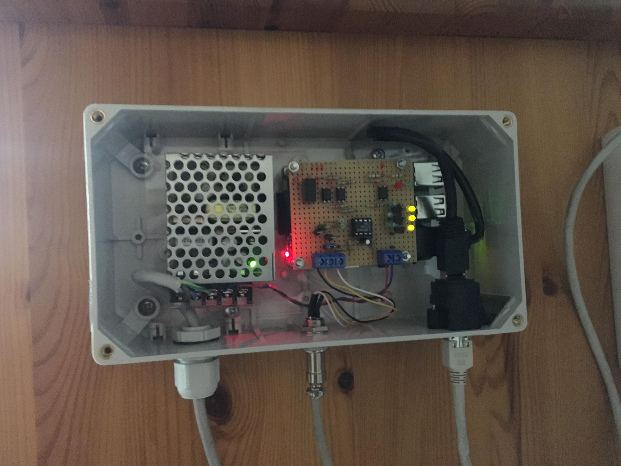
Raspberry Pi mounted Modbus master with power supply.
I built this part of the project before I actually had an application in mind to use it (but sometimes makers work like that).
But I found the application quite soon: I often was annoyed when I went down into the basement in the morning and found all lights left on by the kids. The lights in the basement were not yet connected to a control and/or monitoring system.
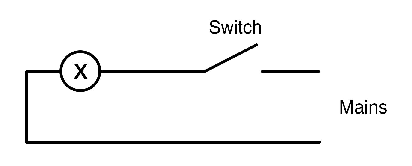
How Do Lamps Switch On and Off in the Installation?
When there is a lamp with one switch it is simple: just a switch will be used:
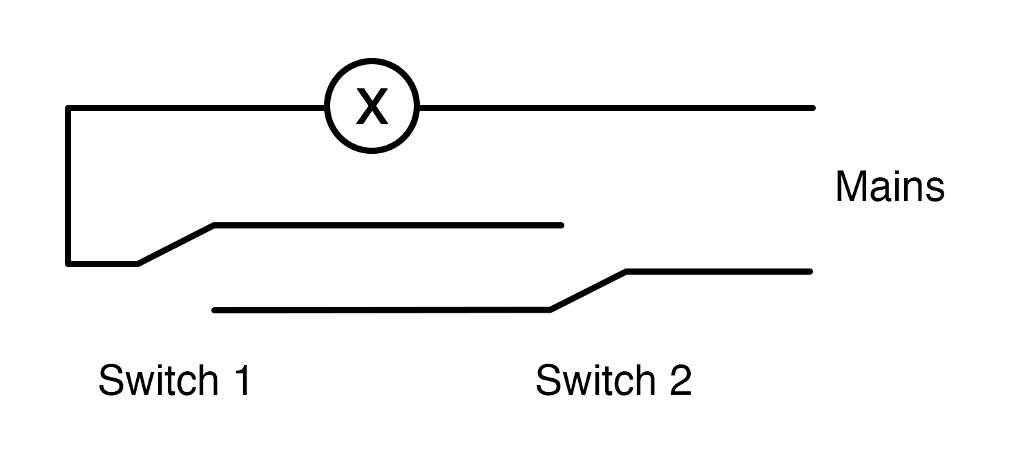
When there is a lamp with two switches, two changeover switches will be used:
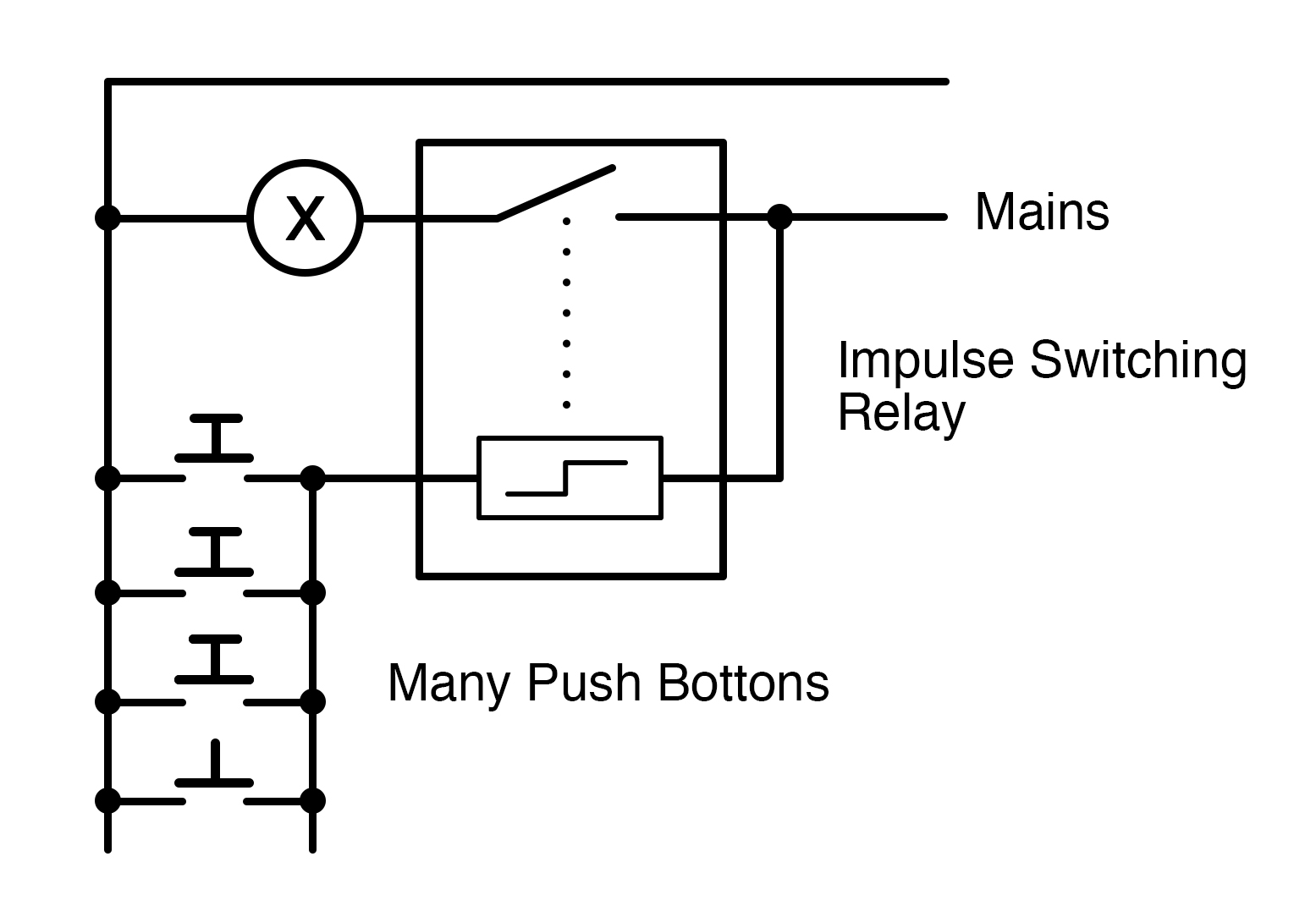
For a lamp with three switches, there is a setup with two changeover switches and a so-called cross switch available, but it is quite uncommon. Usually with three and more switches “Impulse switching relays” are deployed:
At least for two of the four lights in the basement, I had already impulse switching relays in place.
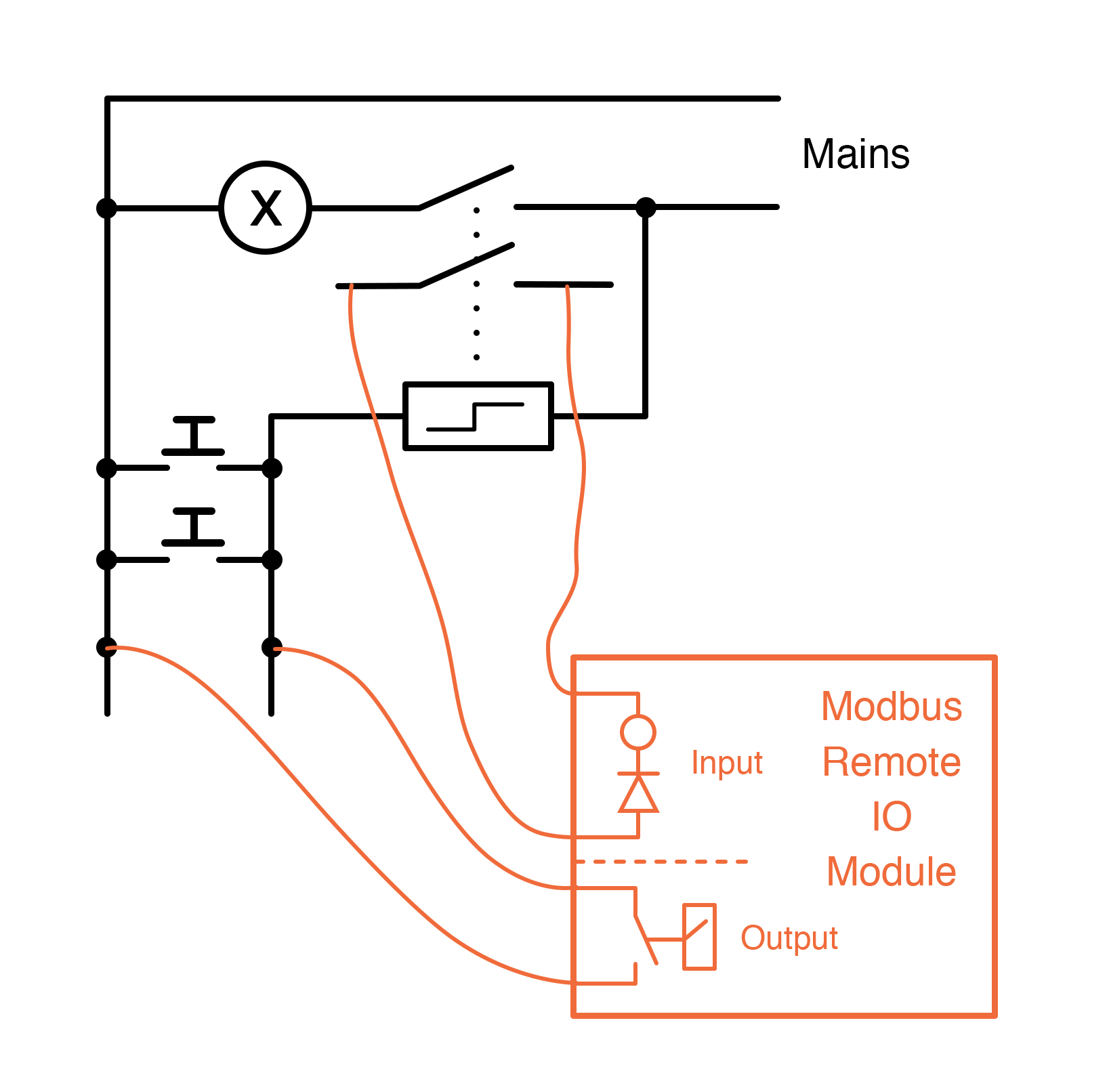
Here I replaced the one-contact relays with two-contact relays and introduced a four-channel Modbus remote IO module:
One lamp, many switches, extended by remote IO module
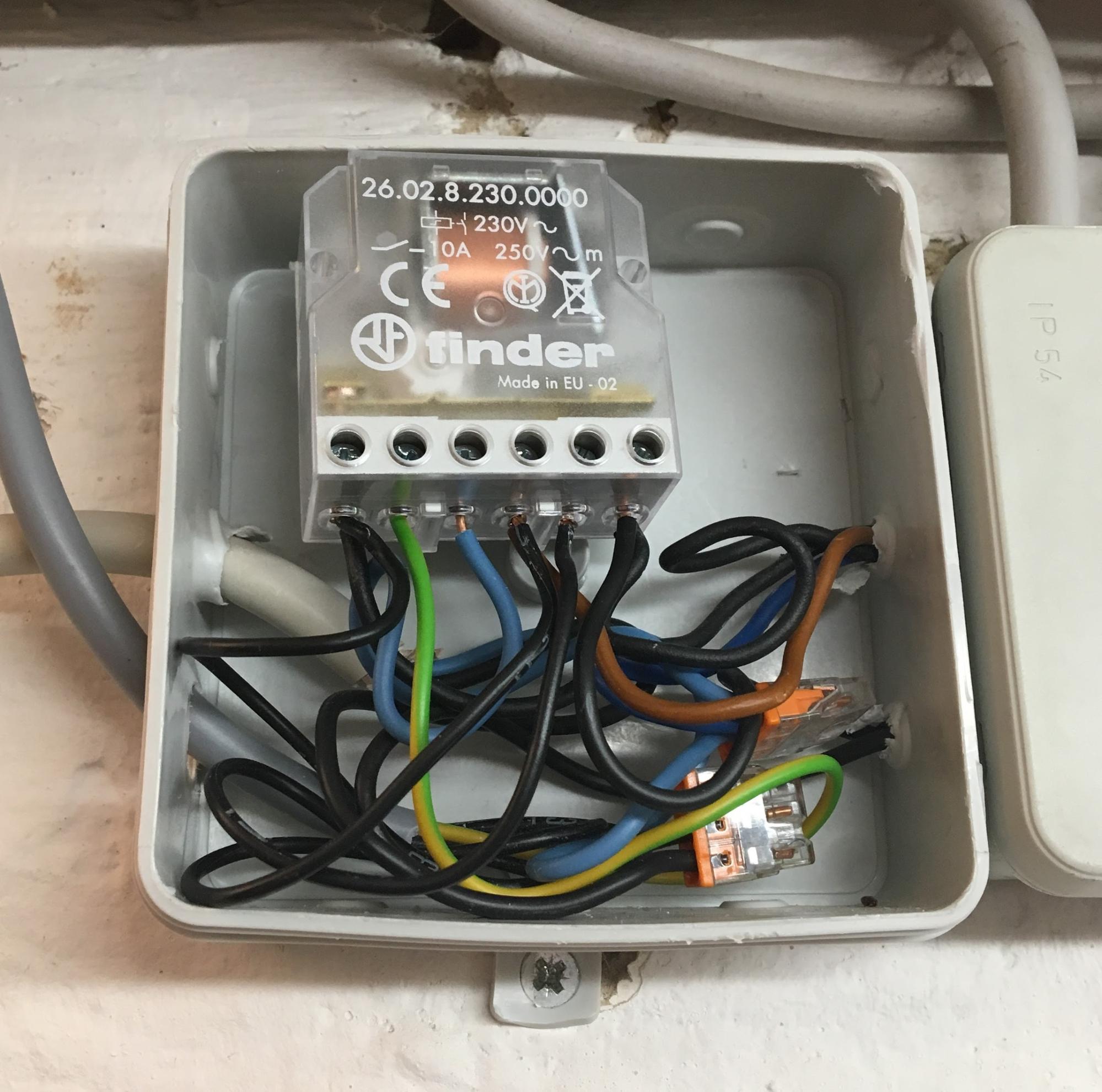
The impulse switching relay I’m using here is the 26.02.8.230.0000 from Finder and the Modbus Remote IO module is the DAM 112 from King Pigeon. However, other relays and IO modules will certainly work as good as these.
Deployed two-contact impulse switching relay
Using the remote IO module I can read the current state of the light via an input channel and I can trigger the relay using an output channel.
Setting Up the NodeRed Application
Since my Modbus master publishes Modbus input registers via MQTT and writes Modbus output registers via subscribed MQTT topics, it was really easy to integrate this setup into my NodeRed application.
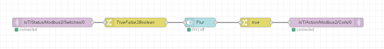
The path of inputs and outputs for my NodeRed application
The trick is here to control the state of the switch node by its input. This input signal is derived from a discrete input register of the Modbus remote IO module which is connected to the second contact of the impulse switching relay. Whenever the switch node is triggered via the NodeRed UI, the output signal and fix set to TRUE which generates a short pulse to trigger the relay via a coil register of the IO module.
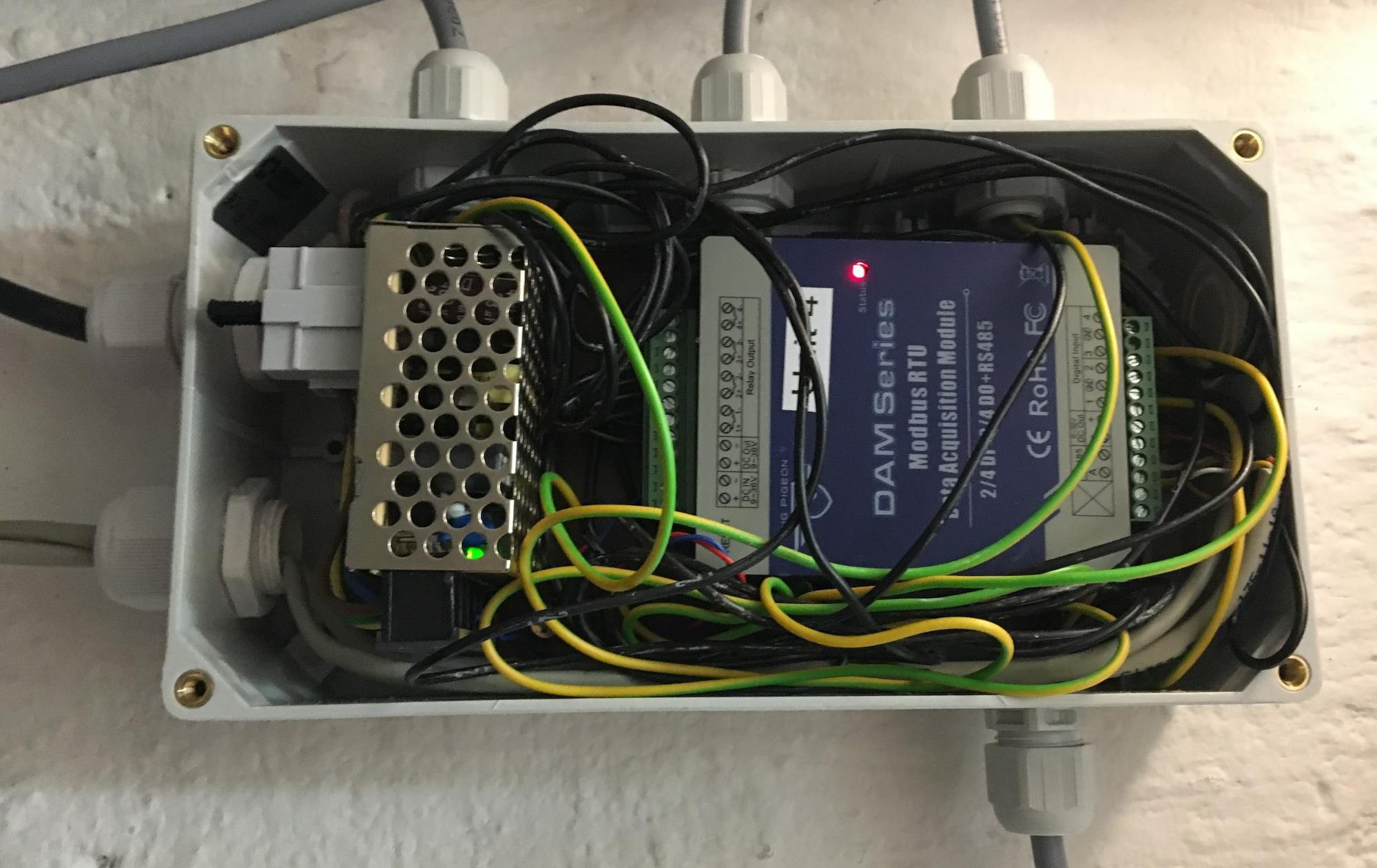
Completely wired Modbus Remote IO Module with power supply
The Final Product
Finally, I got a light switching system:
- with an impressive wife-acceptance-factor. Since your wife/partner doesn’t have to see the new arrangement, the old light switches still work as before
- which is fail-safe: even if the Modbus master or the Modbus remote IO module dies the old light switches directly connected to the impulse switching relays continue to work
- that works in a brownfield environment since those impulse switching relays are quite common in house installations.
If you are not interested in all that Modbus stuff, it is easily possible to control the impulse switching relays with other controllers. You just need one input and one output channel per relay. A very quick search immediately shows a couple of different ESP8266-controlled IO modules.