Set up Python with serial ports — both physical and virtual — to enable your next project!
Python is a useful language thanks to its simplicity, functionality, and platform-independent nature. In this article, we will look at how to use Python with serial ports so you can use it to interact with microcontrollers and other serial-port-enabled devices (including those using virtual ports).
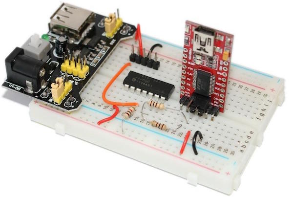
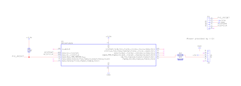
Schematic
Circuit
Getting PySerial
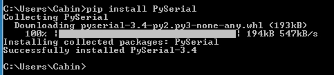
One of the many nice features about Python is how easy it is to install libraries when using the PIP tool. On your computer, open a terminal or command prompt and type in “PIP”. If you get an unrecognized error, then your PIP did not install correctly. When installing Python, make sure that the “Add to environmental variables” option is checked. Once PIP is working, run the command shown below to install PySerial:
With PySerial included in our project, it’s time to open the Python IDLE and create our serial port project!
PySerial
When using PySerial, a few parameters need to be configured (in a similar fashion to setting up UART peripherals on microcontrollers), and these include...
- Baud rate – How fast your COM port operates. Arduino projects tend to operate at 115200
- Port – The name of the port being used (find this in device manager)
- Parity bits – These are used for error correction but are not normally used
- Stop bits – Only one stop bit is ever used unless there are timing issues
- Time out – Used to prevent the serial port from hanging
In addition to defining the parameters shown above, the serial module needs to be imported. The code extract below shows how to import the serial module and configure the UART port to use COM3 at 115200 baud with no parity, one stop bit, and a timeout of two seconds.
import serial

serialPort = serial.Serial(port = "COM4", baudrate=115200,
                           bytesize=8, timeout=2, stopbits=serial.STOPBITS_ONE)
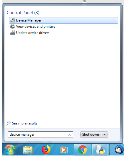
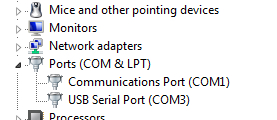
It’s easy to find the COM port your USB-to-serial device is located in when using device manager. Open the start menu and type “Device Manager”. When device manager loads, look for the section called “ports” and expand it. Most Windows machines have a COM1 port by default that is used for internal communication, so don’t use that COM port. Assuming that you only have one COM device connected, the second COM port will be your microcontroller.
Using the serial port is very easy and only requires a handful of functions, including...
- open() – This will open the serial port
- close() – This will close the serial port
- readline() – This will read a string from the serial port
- read(size) – This will read n number of bytes from the serial port
- write(data) – This will write the data passed to the function to the serial port
- in_waiting – This variable holds the number of bytes in the buffer
In our simple program, we first open the serial port defined previously. It is imperative that the open() function is called, because it allows our program to “claim” the port and prevent any other processes from accessing it. A port also cannot be accessed if it has not been opened.
- The next piece of code is an infinite loop, which does a few things...
- Checks to see if there is any data waiting in the buffer
- When data has arrived, transfer the data to the variable “serialString”
- Print the value of “serialString”
- Write a string back to the device that sent the data informing it that we received the string
serialString = ""                           # Used to hold data coming over UART


while(1):

    # Wait until there is data waiting in the serial buffer
    if(serialPort.in_waiting > 0):

        # Read data out of the buffer until a carraige return / new line is found
        serialString = serialPort.readline()

        # Print the contents of the serial data
        print(serialString.decode('Ascii'))

        # Tell the device connected over the serial port that we recevied the data!
        # The b at the beginning is used to indicate bytes!
        serialPort.write(b"Thank you for sending data \r\n")
Our Microcontroller Circuit/Code
To test our Python serial port program, we will be using a very tiny PIC chip, the PIC16F1825, which will be coded using XC8. This chip has a UART port which means we can connect it directly to a USB-to-serial converter (such as the FTDI 232R). Luckily for us, the FTDI module used here provides power from the USB port so we do not require any power circuitry (easier to construct).
The code for the PIC is comprised of three main areas:
- Configuration bits – These configure core registers such as PLL and oscillators
- Main Code – The main execution code (found in main())
- Functions – These include writing strings to the UART and configuring the UART
The configuration bits will not be covered in depth, but they ensure that the PIC is NOT using the PLL, but is using the internal oscillator module as its clock source.
// CONFIG1
#pragma config FOSC = INTOSC pin)
#pragma config WDTE = OFF
#pragma config PWRTE = OFF
#pragma config MCLRE = ON
#pragma config CP = OFF
#pragma config CPD = OFF
#pragma config BOREN = OFF
#pragma config CLKOUTEN = OFF
#pragma config IESO =
#pragma config FCMEN = ON

// CONFIG2
#pragma config WRT = OFF
#pragma config PLLEN = OFF
#pragma config STVREN = ON
#pragma config BORV = LO
#pragma config LVP = ON
The main function is where the PIC does three things: configures the device to use a clock frequency of 8MHz (for the UART Module), configures the UART peripheral; and then sends/receives strings over the UART port. The actual functions that read and write strings have been defined in functions, which make it easier to use the UART port in the main code, but we won’t cover the explanation of this code.
void main(void)
{
    // Configure pins as digital
    ANSELA = 0;
    ANSELC = 0;

    OSCCONbits.IRCF = 0b1110;

    configUART();

    while(1)
    {
        sendStringUART("Hello, this is the PIC16F1825");
        readStringUART(stringBuffer);
    }
}
The functions provide useful features, and below are the function prototypes:
void configUART(void);
void sendByteUART(char data);
void sendStringUART(const char *string);
void readStringUART(char *buffer);
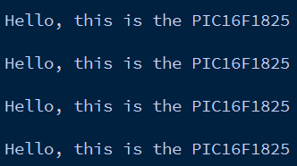
The Result
If all goes to plan, when the Python program runs and the PIC device is turned on, we should see something similar to the window shown below. If so, then our PIC program and Python program are communicating perfectly with each other. While this example is very simple, it shows that Python can easily be integrated into microcontroller projects, including PIC, AVR, STM, Arduino, and even Raspberry Pi!