Raw Data Transfers
Modern microcontrollers will usually have many device interface peripherals built into them, including I2C, SPI, UART, and CAN. While I2C and SPI are very specific to devices and heavily rely on either select signals or start/stop signals, UART is more free. One of the biggest disadvantages of UART is the lack of a clock signal, which can result in clock drift of either the transmitter or receiver (which results in a baud difference), frame errors, and even overrun errors when one of the buffers on either side is full. Of course, these problems are relativity easy to overcome with the use of timers, watchdogs, and events. But serial connections are more commonly found in one particular scenario, unlike I2C and SPI: removable hardware. I2C and SPI devices are usually ICs directly soldered to the main circuit board or permanently connected to them. At the same time, these devices are children to the main controller and thus can never initiate a data transfer themselves.
Imagine a PIC and computer communicating over a serial connection where each device can send either commands or data to the other device. Such a system could easily be implemented with a trivial message protocol where the first byte sent represents the command, and the following bytes represent data for that command. As long as there are no interruptions, this system works without any issues. However, what would happen if the computer crashed and restarted while it was halfway through transmitting data bytes after sending a command? Well, our program would restart and try to send a command byte to initiate a data transfer, but the command byte would be interpreted as a data byte by the PIC, as it was still expecting a data byte. This results in the PIC producing errors, as the bytes it reads may produce unexpected results. But this is not just a problem for UART; any connection that can potentially be terminated, with no way of knowing that the connection has been terminated, can also crash. The solution is to use a message protocol!
Our Message Protocol: DHP – DIY Hacking Protocol
To ensure that commands are always processed properly, command byte values will be unique. For our system, we will have the following commands:
- 0x00 – No operation
- 0x01 – Request data
- 0x02 – Write data
- 0x03 – End of data
- 0x04 – Restart (error or fail occurred)
As a simple example, if we want to send some data to the PIC via the computer, we have to start by sending 0x02, then all the data, and then an end-of-data byte. If the transmission is interrupted and the computer attempts to resend the data, it would send the entire packet all over again. The PIC would correctly interpret the command byte and realize that a new packet is being sent. However, what happens if our data contains 0, 1, 2, 3, or 4? The PIC will interpret these as command bytes, and thus a fatal error will occur. So, how do we get around this?
While not the most efficient method, we can instead represent our data in some other form as opposed to raw byte values. One method is to represent our data as ASCII characters in hex form so that two ASCII bytes represent one byte of data. For example, FF represents 255 where 00 represents 0. Therefore, our data bytes can never be the same value as command bytes, and by using ASCII-encoded hex bytes, we can theoretically have up to 240 command bytes (leaving 16 hex chars for data). The disadvantage of using ASCII-encoded data is that we have effectively halved our data rate, and the command bytes further reduce the speed. But at the same time, the reliability of the system has been significantly improved.
How about data integrity? We can accomplish this by adding a checksum to our data package so the receiver can ensure that the data is intact. One easy way of doing this is to XOR all the bytes received and use that as a checksum. If any single bit has been misread, this will show up in the XOR checksum. If two bits in the same column have been misread, then the checksum remains unchanged, so XOR is only effective for single-bit errors (but these are the most common).
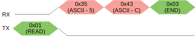
Example Packages
Writing the number 92 (hex 0x5C)
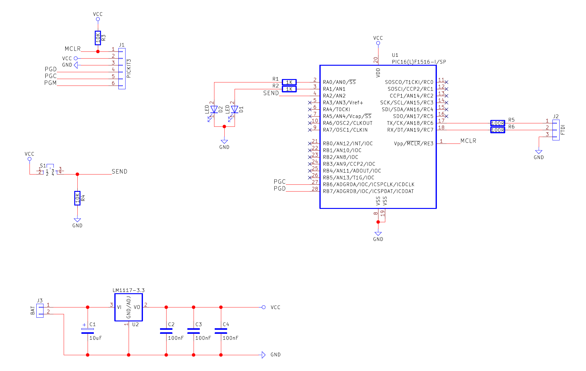
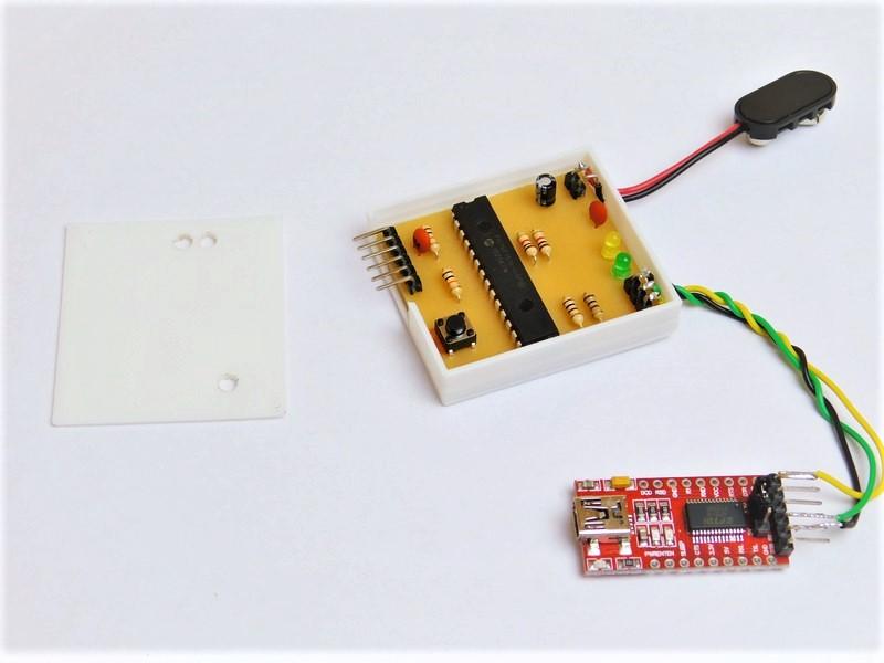
Construction
This project can be built using many different circuit construction techniques, including stripboard, matrix board, breadboard, and PCBs. In this example, I have used a PCB made on a CNC machine (via isolation routing), but I am considering going back to a chemical process, for reasons that will be discussed in a later article.