Save yourself some time and heartache by building your own IC tester to use on your projects!
ICs are used in almost every electronics project, but trying to determine if an IC is working or not can be a challenge. In this project, learn how to create a simple IC tester using an FTDI, PIC18 IC, and some VB.net coding!
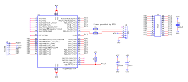
Schematic
The IC Tester Circuit
This IC tester is incredibly simple and is comprised of two main units:
- A PIC18 chip with its GPIO connected to a DIP20 socket and UART USB connectivity
- A VB.net program that can configure the GPIO
When the PIC18 boots, it starts by executing configuration code that sets up the internal oscillator, the UART module, and the GPIO. Once booted, the PIC waits in a loop and reads commands over the UART peripheral. These commands include:
- D – The PC has finished sending all of its data and is ready to test the IC
- R – Reset buffers and prepare for new data
- 1 – Set pin to input or logical output 1
- 0 – Set pin to output or logical output 0
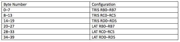
Twenty GPIO pins are connected to the DIP20 socket, which includes PORTB, PORTC, and PORTD, and once all the data has been streamed in, the PIC configures the GPIO to test the IC. For proper configuration both TRIS and LAT registers need to be configured, and to do this the PC streams 40 bytes where the first 20 bytes configure the TRIS registers and the second 20 bytes configure the LAT registers.
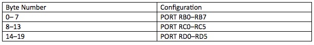
Once all the GPIO pins have been configured, the PIC streams back 20 bytes that represent the states of the GPIO pins (which is done by reading PORT registers).
This IC tester can be used to test devices that consume less than 10mA, which include 7400 and 4000 series devices. The GPIO on the PIC18 can even power the VCC and VSS lines directly, but remember to follow the rules listed below:
- VCC Pin – Configure PICs pin as an output and set LAT bit to 1
- VSS Pin – Configure PICs pin as an output and set LAT bit to 0
- Input Pin – Configure PICs pin as an output and set LAT bit to x where x is test variable
- Output Pin – Configure PICs pin as an input
- This IC tester cannot test open collector outputs
The IC Tester Program
The program that controls our IC tester is written in VB.net and is a form application, which makes making GUI apps very easy. I should note at this point that this is far from a complete program and could be drastically improved! The main window has two tabbed pages:
- IC Test – This is used to test an IC
- Create Test – This is a simple application that makes writing tests slightly easier
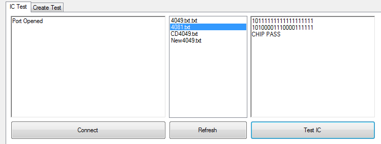
IC Test
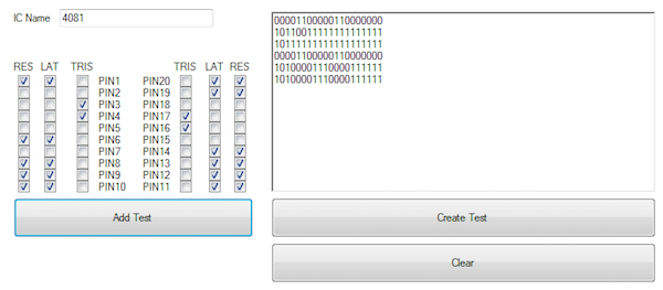
The “Connect” button is used to connect the VB.net program to the FTDI COM port that needs to be determined before compiling the program (you can easily find the COM port by going to device manager and looking for connected ports). Once a connection has been established, the “Refresh” button is used to display a list of files that represent IC tests. By default, this project comes with two ICs: the 4081 quad AND gate, and the 4049 hex NOT gate. Select one of the IC tests in the list, and place your IC in the 20DIP socket with both pin 1s in the same place. Then press “Test IC”, and the program performs the tests.
Test files consist of lines where every three lines represents a single test. The first line contains TRIS configuration data (20 characters either 1 or 0), the second line contains LAT configuration data (20 characters either 1 or 0), and the third line contains the expected results from the PORT registers (20 characters either 1 or 0).
When you execute a test, the program first determines the number of lines in the program and divides this number by 3; this represents the number of tests that need to be executed. Then, each test is performed, and if any single test fails (e.g., the 20 bytes from the PIC don’t match the line in the file), then the test fails and returns an error code. If all the results come back as expected, the IC has passed!
Create Test
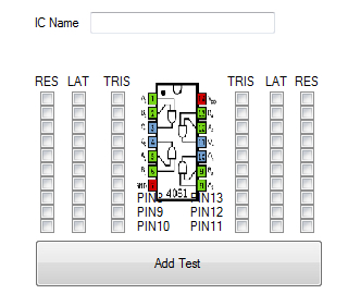
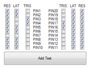
The “create test” tab is used to create IC test files. While these can be written manually, it can be very tricky to visualize which bits are controlling which pins and what their expected values should be. Therefore, the create test page can be used to do just this. The page shows many check boxes that represent TRIS (the direction of the GPIO), LAT (the value the GPIO needs to output), and RES, which is the expected result of that pin (on or off).
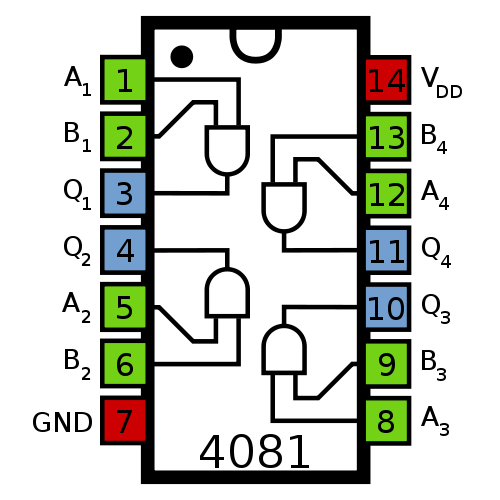
To best understand how to use this, let’s create a test for the 4081 IC. This IC has four AND gates, so we will do a simple test that will try to turn on all the outputs for the AND gates. The image below shows the pinout and an overlay on the create test page so you can see which GPIO connect to which pins.
To turn on the outputs of the AND gates, we need to turn on both inputs, so we need to set the corresponding pins to be outputs (setting the TRIS box to unticked which represents 0). Outputs from the AND gates will be read by GPIO, so these TRIS bits need to be checked, which represents a 1. Since we will be feeding 1 to all the AND gate inputs, we will also need to check their corresponding LAT bit (this makes the GPIO switch to VCC).
VCC and VSS both need their TRIS bits cleared, but only the VCC pin (pin 20) will have its LAT bit checked, because VSS needs to be connected to ground, and this is done by setting that GPIO to 0. Below is the complete check setup for a 4081 quad AND gate, which checks for AND gate functionality when both inputs are on.
Unused I/O need to be set to be outputs, and their output bit needs to be set to 1 as well as the expected result. To add this test, click “add test”. But we can add more tests to the same IC by changing the check boxes and clicking “add test”. So we will add a second test that checks to see if the AND outputs switch off when one of the inputs goes off.
Now that we have two tests, we can click “Create Test”, which will produce a text file that will contain our six lines of data that represent two different tests, and the system will only pass the IC if it passes both tests!
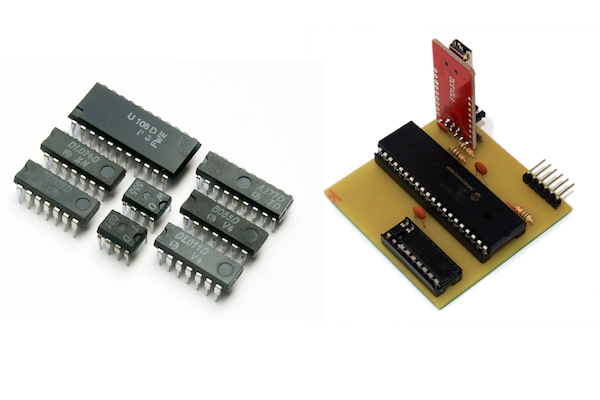
Construction
This project can be constructed using most methods of circuit construction and is very easy to build. The board gets power from the FTDI 232 USB-to-serial converter, which removes the need for power circuitry, and the PIC is only connected to a programmer, serial port, and the DIP 20, so this project would be very easy to make using wires.
Circuit construction technique suitable for this project includes stripboard, breadboard, matrix board, and even PCB. I used a PCB for this project, as I don’t particularly like wiring circuits, and I wanted to test some dry film solder mask that I purchased. It worked out well!