In this article, learn about another useful peripheral for PIC microcontrollers: timer0 and the watchdog timer.
In the last article, we looked at the ADC peripheral and how it can be used to make analog measurements. In this article, we will look at using timers and the watchdog timer in PICs.
Catch up on the rest of the PIC microcontroller series here:
Timers are for Timing!
In many PIC examples, you will see delays that are designed to add pauses during code execution. One example of such a delay includes the LED flashing code in the previous articles, which use a simple for-loop to add a delay between the ON and OFF states of the LED. However, sometimes such delays are not very useful, especially when accurate timing is needed.
When accurate timing is a necessity, very useful peripheral comes in: the timer! Unlike for-loop delays, a timer can provide a very accurate source for timing events and creating delays of a specific length. Typically, PICs have many different timers, so to keep things simple, we will only be looking at timer0 and the watchdog timer in the PIC16F819.
Timer0 in the PIC16F819
Most PICs have a timer0, which is usually an 8-bit timer that can be clocked from multiple sources, is used for other peripherals, and can generate interrupts upon overflowing. This makes it very useful for crucial timing routines, but can be used as a generic timer as well. When using the timer, there are two main ways which this can be done:
- Interrupt the PIC when the timer overflows (counts over 255 and resets back to 0)
- Probe the timer register and see what value it is currently at
Since we have not considered interrupts yet, we will focus on using the timer to make a simple 1ms delay via polling. The first task when using the timer is to configure, which is done by configuring registers associated with the timer. For the PIC16F819, the OPTION_REG holds the bits needed for configuring the timer.
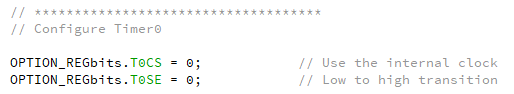
The first bit that needs setting is the clock source for the timer. The most common source is from the internal instruction clock cycle (essentially the operating frequency/4), but you can also clock the timer from an external clock source (which is fed into the T0CKI pin). In our example, we will clock it from the PIC and NOT an external source.
The next bit that can be set is the clock edge, which determines if the timer increments on a rising edge or falling edge; this is rarely used and so can be ignored for now.
The next bit, PSA, determines if the pre-scaler is assigned to the timer or to the watchdog. In this example, we will assign the PSA to the watchdog for reasons that will be explained later.
Setting up timer0 on the PIC16F819 in XC8
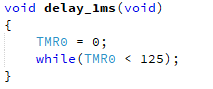
With the timer configured, it's time to use it in some code to make a 1ms delay. The timer is clocked from FOSC / 4 and with our FOSC being 500kHz, the timer will therefore increment at a rate of 125kHz (or once every 8us). As we want to make a delay of 1ms using this timer, we need to determine how many times the timer will clock until it reaches a value that is approximately 1ms. This is where a bit of mathematics comes in!
Therefore, the timer will have a value of 125 when 1ms has passed. So in our delay function, we reset the timer value and then wait until the timer register is equal or greater to 125.
The Watchdog Timer in the PIC16F819
The watchdog timer can be a real source of pain and can also make a PIC system incredibly robust and reliable. But what exactly is the watchdog timer? Simply put, the watchdog timer is a hardware timer in the PIC that, if not constantly reset by the software, will cause the PIC to reset. This feature can be incredibly useful if the PIC should hang due to a hardware or software issue and guarantees that the PIC will restart from the beginning. Not only does it reset the system, it also flags a bit that can be used to determine if the system just crashed.
Before the watchdog can be used, it has to be enabled, which is done by setting a configuration bit at the top of your code. If you are not using the PIC16F819, either check your datasheet on which configuration bit is used, use the configuration bit selection system in MPLAB X, or Google it.
Turning on the watchdog timer on the PIC16F819
The next step is to check if the watchdog is being used with the pre-scaler or not; this is where the OPTION_REG from before comes into play. Since we did not want the pre-scaler used with timer0, we set the PSA assignment bit to 0, which means that the pre-scaler is assigned to the watchdog. But how does this affect the operation of the watchdog? Essentially, the pre-scaler can be thought of as a clock divider so if you have a 1MHz clock going to the watchdog that has a 2 x pre-scaler, the clock going into the watchdog is actually at 500kHz (since it’s divided by 2).
The watchdog takes its clock source from the internal 31.25kHz oscillator, has a 16ms period, and this 16ms pulse is then fed into a pre-scaler system. This means that the watchdog can time out on one of 8 different options (assigned using the PS2:PS0 bits).
000 – 16ms
001 – 32ms
010 – 64ms
011 – 128ms
100 – 256ms
101 – 512ms
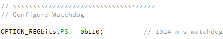
110 – 1024ms
111 – 2048ms
For our project, we will configure the watchdog timer, so if the project hangs for more than a second, the system will reset.
Setting pre-scaler which has been assigned to the watchdog
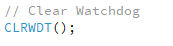
So now we have a watchdog that will reset the PIC once a second when it hangs, but how do we determine a hang? This is where a useful function comes in: CLRWDT(). Once this function is called, it will automatically reset the watchdog timer. This function should be placed in a main loop code section so that for the PIC to not reset, the main code needs to be iterated once every so often.
The function needed to reset the watchdog timer
Timers: An Essential Peripheral
Timers can be fantastic peripherals that you should take advantage of as soon as you can. They can provide for accurate timing, counting, and even hang-free systems. PICs sometimes have other timers that come with many advanced features, such as 16-bit and gate control, which can be used to control other peripherals. Overall, don’t hesitate to use timers!