Learn about ADCs and how you can make analog measurements from the pins of your PIC microcontroller.
In the last article, we looked at how to use I/O pins on the PIC16F819 in XC8 as well as configuring the internal oscillator. In this article, we will look at the ADC and how it can be used to make analog measurements from pins.
Catch up on the rest of the PIC microcontroller series here:
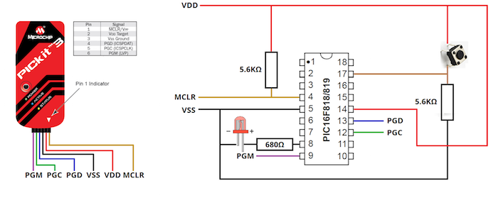
Schematic
Software Downloads
Microcontrollers are digital devices that operate on digital information. Because of this, they easily interact with digital circuits and systems where all information is binary. However, not all circuits are digital, and despite what you may see in the news, analog will never disappear! So, how can a digital system such as a microcontroller interact with an analog system?
The answer is in one of the most common peripherals; the Analog-Digital Converter, also known as ADC. The job of this peripheral is to convert an analog reading to a digital result that can be used by a CPU, and this digital result is typically a binary number between 8 bits and 12 bits in length. ADC modules can be complex in nature, and there are many different ways they can be built. Due to their complex nature, they will not be described in detail, but some of the more common conversion techniques include Flash ADC and Successive Approximation.
Since ADCs convert analog information into digital information, there are a few issues that need to be understood. First, analog information is continuous (1, 2, 3.1415, etc.), whereas digital is discrete (1, 2, 3, 4), which means that there will be a finite smallest amount that the digital measurement can count. This is usually referred to as the resolution of the ADC and will be covered in a simple example later. The second issue that you need to remember is that ADCs require references and have a fixed bit width, which will determine the resolution and the range that it can detect. Third, ADCs in a PIC usually have a minimum acquisition time, which means that the ADC needs a small amount of time to do its calculation to convert the analog value into a digital number.
ADC Practical Considerations
So how do we determine the resolution and acquisition time for our ADC? The first step is to read through the ADC chapter in the datasheet of your microcontroller, because they can all be different! But if you are using the PIC16F819, you are in luck, because I read it all for you! That’s right, for you!
With that chapter read, we will now determine the smallest voltage change that the ADC can read. So to do this, we need to determine our reference voltage. The PIC has some pins that can be connected to an external reference, so you can take measurements from isolated external analog circuits. These two pins are called AVSS (negative reference) and AVDD (positive reference). However, in most cases these pins are not needed because the input analog measurement is within the supply voltage of the device (in our case, 0V to 5V). Therefore, we can internally connect the ADC reference pins to VSS and VDD of the PIC using the ADCON1 register!
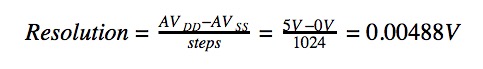
So we have determined that our reference for the ADC will be the supply voltage (0V to 5V), which means that the lowest voltage the ADC can measure will be 0V and the largest voltage that the ADC can measure will be 5V. But what is the smallest change in voltage that the ADC can measure? To find this out, we need to know the resolution of our ADC, or how many digital points there are. Looking at the datasheet, the PIC16F819 has a 10-bit ADC, which means that all digital readings from the ADC are 10 bits in length. The largest number than can be expressed in 10-bits is 1111111111 or 1,023, and if we include 0 as a step, the total number of individual states is equal to 1024 (210). Therefore, a 10-bit ADC has 1024 discrete voltage steps that it can measure! So the smallest step is simply the difference in the reference voltages divided by the total number of steps.
What about acquisition time? This factor is somewhat more specific to what circuit is connecting to the microcontroller and how fast the microcontroller operates. For situations that don’t rely on high speed conversion you can select a long acquisition time to guarantee that the ADC performs without error. If, however, you want to push the ADC to its limits, you need to consult the devices datasheet on maximum speeds and minimum acquisition times.
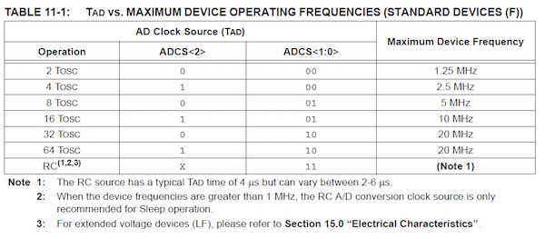
In the PIC16F819 the acquisition time is calculated using the complex formula on page 84, but page 85 has a useful table against chosen acquisition times (when using TOSC) and the maximum operating speed.
ADC clock speed and resulting maximum device speed
PIC16F819 ADC in XC8
So now that we know a little about ADCs, it's time to use the ADC in the PIC16F819! To get the ADC to work, we need to do the following tasks:
- Configure I/O pins as analog input(s) and configure ADC reference
- Configure ADC registers to choose an analog pin
- Configure ADC registers to enable the ADC
- Configure ADC registers to set the acquisition time
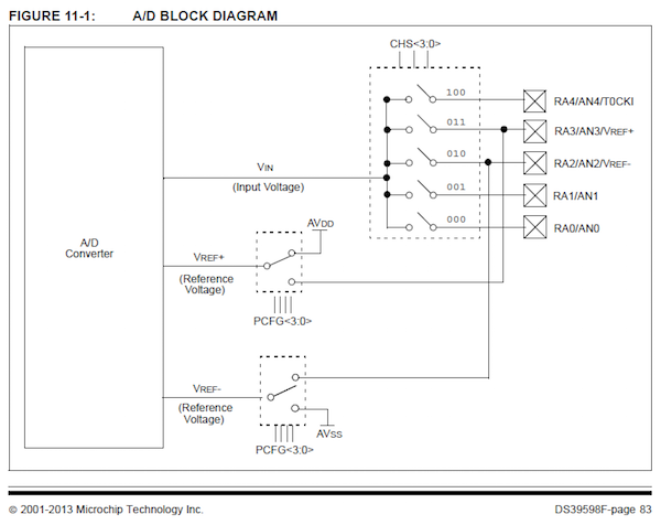
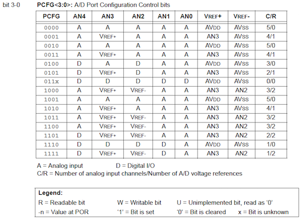
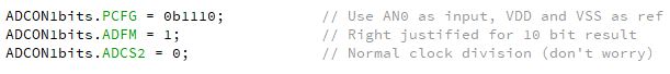
In our program, we will read from the analog pin AN0, which is found on RA0 (pin 17). Therefore, we need to configure that pin to be an analog pin, and to do that, we need to set some bits in ADCON1. Page 82 in the PIC16F819 datasheet has a table of what each bit in ADCON1 does, and the lowest four bits (3 to 0) control the analog inputs as well as where the ADC gets its reference from. Since we want AN0 to be an analog input as well as VDD and VSS as our reference, we will use the value 1110 (second to bottom row).
Extract from datasheet showing different analog configurations.
There are two other bits that we will set in the ADCON1 register: ADFM and ADCS2. ADFM determines if the ADC result will be either left or right justified. THIS IS REALLY IMPORTANT! Sometimes a 10-bit result is too much and an 8-bit result would suffice. When this bit is set to 0, the upper ADC result register can be read directly to produce an 8-bit result (this discards the lower bits). While this reduces the resolution of the result, the result can now fit in an unsigned char variable, which is only 8 bits in size and is the fastest data size to operate on. In our project, we will not worry about this, so we will set it to 1. The clock source bit is not too important, so just set this to 0 for now.
The next task is to configure ADCO0, which has a few bits that require setting.
The first two bits that require setting are clock source bits. While these may be important in other projects with timing considerations, they are not important in this tutorial. Therefore, we will use the ADC’s internal RC oscillator by setting the ADCS1 and ADCS0 bits both to 1.
The next two bits that need setting are the channel selection bits; these determine which analog input we are reading from. While there are many analog inputs, only one can be connected to the ADC at any time. So to connect a specific input to the ADC, we have to select that channel! Since we are using AN0 we will use Channel 0 (000).
The last bit that needs setting is the ADON bit, which essentially turns on the ADC module.
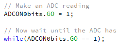
The last step is actually using the module! While the theory and configuration may seem difficult, using the module is actually very easy. In our code, all we have to do is set the GO bit in ADCON0 and then wait until that bit resets back to 0 (as seen below).
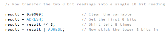
With the reading complete, it’s time to read it. The issue with the PIC16 and PIC18 devices is that they are 8-bit devices, which means that all of their registers are 8-bits wide. Therefore, the ADC has two ADC result registers, with the first register holding the first 2 bits of the result and the second register holding the last 8 bits of the result. If the ADFM bit was set to 0 then the first register would hold the first 8 bits and the second register would hold the last two bits.
Since we will use the entire 10-bit result, we need to take both numbers from the two result registers and then combine them into a single number. To do this, we start by loading the upper portion of the number first (ADRESH), and then shift this number left 8 times. The next step merges the lower 8 bits into the result variable that holds the entire 10-bit result.
Reading the 10-bit result
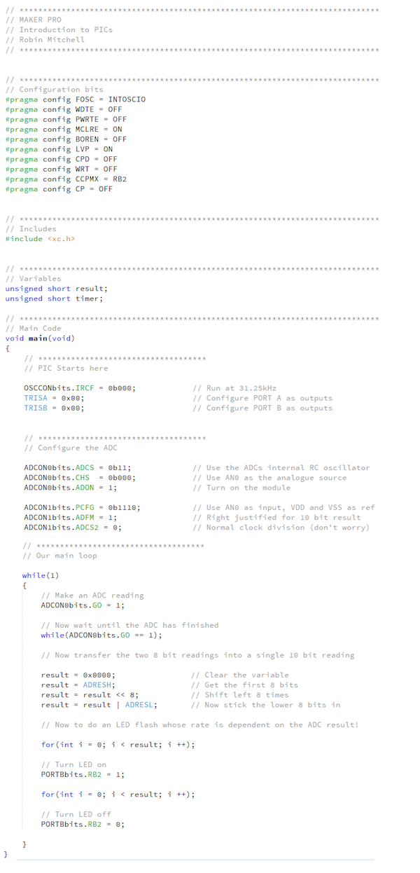
Complete Code Example
Final Thought: 8-Bit Result Reading
For those who want simpler and faster code (by sacrificing on the resolution) you can read an 8-bit ADC result instead. To do this, you need to set the ADFM bit to 0. To read the ADC result, use the following code.
8-bit ADC result when ADFM=0