This article introduces interrupts and how they can be used to improve your PIC microcontroller programming.
In the previous articles, we looked at how to use MPLAB X and XC8 to program PIC16 devices. In this article, we will look at interrupts and how they can be useful.
Catch up on the rest of the PIC microcontroller series here:
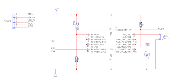
Schematic
Polling Just Isn't Enough
Imagine a scenario where we have a PIC device that needs to do something when it receives a digital signal on one of its pins. This could easily be implemented using a while loop that probes an input pin, and if that pin reads a particular digital level, the code can execute some response code. However, this method of detection has a few issues:
- Polling can be potentially blocking
- The signal could be missed
When the PIC polls the pin and detects that the desired input has not been met, the PIC simply sits in the loop until it detects the signal. This means that no other code can execute until the input has been detected, and this is potentially wasteful. If that is not irritating enough, what about fast external signals? If the input signal on the PIC’s pin is too fast, it may not be detected, which means that valid input pulses are being ignored. So, how do we get around this? Is there a way to detect inputs and other events that don’t block our PIC so it can do other tasks while waiting? This is where interrupts come into play!
The Role of Interrupts
Most, if not all PICs, have a feature called interrupts that force the PIC to do a specific task when an interrupt signal is detected. So take the example that we had before, where the PIC needs to do a specific task upon detecting an external signal.
Instead of polling, we can define an interrupt routine that runs when any interrupt is received. Then, inside this interrupt service routine (ISR), we can check to see if an external signal was detected. If it was, the PIC can be made to run some response code, else we can ignore the interrupt (since it could have come from another source that we are not interested in). In the main code, we do not do any polling at all, as it is all handled by the hardware and interrupt routine that we defined.
However, you must understand that the interrupt service routine does not run at the same time as the main code that the PIC executes; instead, the PIC stops running the main code, runs the interrupt service routine, and then resumes the main code. This is why interrupt service routines should be as short and fast as possible since they block the main code when they run.
Some PIC devices have interrupt priorities, but for now, we will only consider the PIC16F819, which does not have interrupt priorities.
Coding the Interrupt Service Routine (ISR)
Now that we have a basic understanding of how interrupts work, let’s see how we program a basic ISR for the PIC16F819 using XC8. The neat feature about XC8 is that it handles a lot of nitty gritty requirements such as context saving so we only have to worry about setting up interrupts and writing how the PIC will behave when an interrupt is detected.
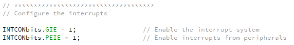
The first task is to enable the PIC’s interrupt mechanism as well as enabling peripheral interrupts. Most PICs have a register called INTCON and this register holds the most important interrupt information. GIE is the bit responsible for enabling interrupts in the first place, whereas PEIE is used to enable interrupts from peripherals (including the INT pin, ADC, SPI, I2C, and I/O change).
The next step is to enable the INT pin interrupt, which is done by setting the INTE bit in the INTCON register. The INT pin is located on RB0, which is pin 6, and we also configure this pin to be an input by ensuring that its TRIS bit is set (covered in a previous article).
One other bit that we can change is the INTEDG, which is found in the OPTION_REG register. When this bit is set, the interrupt will fire when the digital signal on the INT pin goes from a logical 0 to a logical 1 (rising edge). When this bit is cleared, an interrupt is fired when the signal goes from a logical 1 to a logical 0 (falling edge).
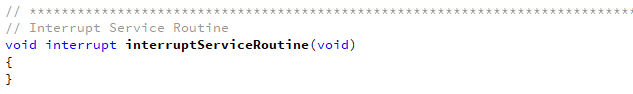
With these bits configured, the PIC will now perform an interrupt routine when the INT pin detects a rising edge signal. But what code? Where is the ISR? This is where XC8 makes things really easy! All we need to do is define an interrupt function, and XC8 is clever enough to tell the PIC to put the code in the right place so that the PIC executes it upon receiving an interrupt. Below is an empty interrupt service routine and shows how interrupt routines are defined in XC8.
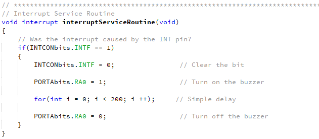
Of course, this routine is empty and would cause some problems. When an interrupt is fired, a flag bit is set. When our ISR starts, we need to clear these interrupt flag bits, otherwise, the ISR would run again as soon as it finishes (it’s the flag bits that fire the interrupt!). So, in our ISR, the first task is to check to see if the INT flag has been raised (equal to 1). If it has, we will clear it and then do our response code.
All interrupt sources have interrupt enable bits and interrupt flag bits, and you can find which registers these reside in by using the datasheet. In this example, we briefly turn on a buzzer that is connected to RA0 when a rising edge is detected on the INT pin.
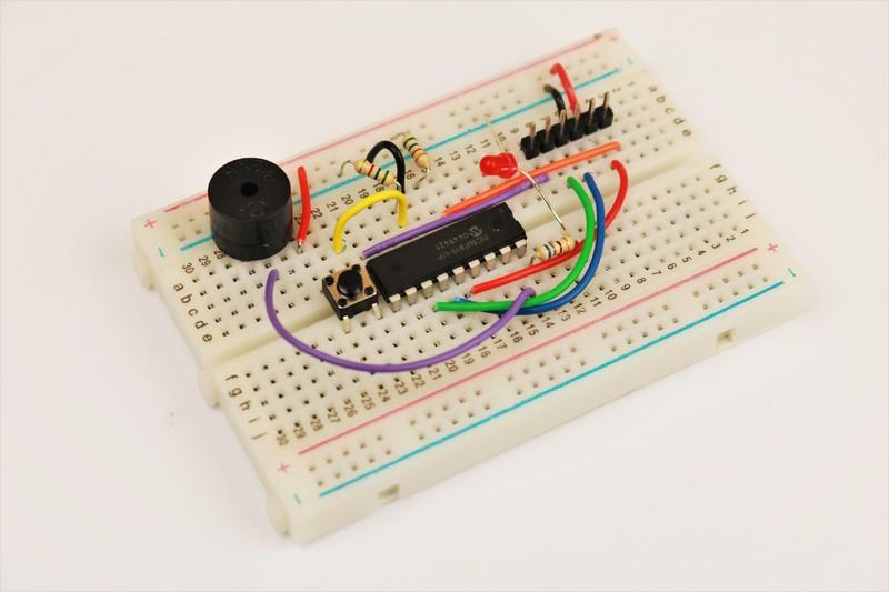
Our Interrupt Example
In our example the PIC does the following tasks:
- Flashes an LED (in the main code)
- Makes a short beep when a rising edge signal is detected on INT (RB0) (interrupt response)
The key feature about this program is that the LED code will constantly run until an interrupt is detected, in which case the ISR is executed. Once the beep sound (the ISR) has been done, the PIC resumes normal operation and carries on with the LED flash sequence. Note that the PIC can still detect interrupts during its for-loop delays in the main code. This way, the delay cannot block the detection of input signals.