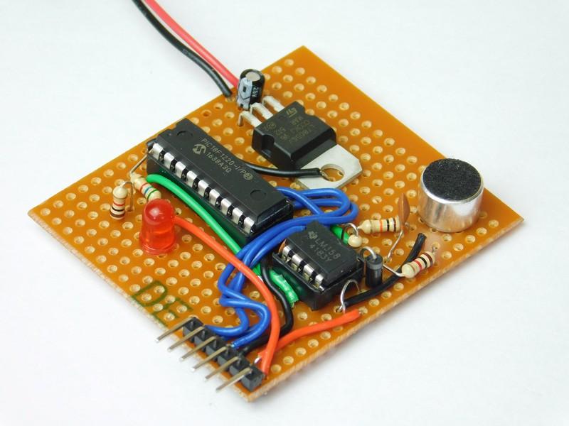
Create a circuit that can detect flying bugs that buzz.
If you, like most, are irritated by fly insects or have a fear of being stung by a spiteful wasp then this circuit is for you. In this project, we will create a circuit that can detect flying bugs that make that distinctive buzz!
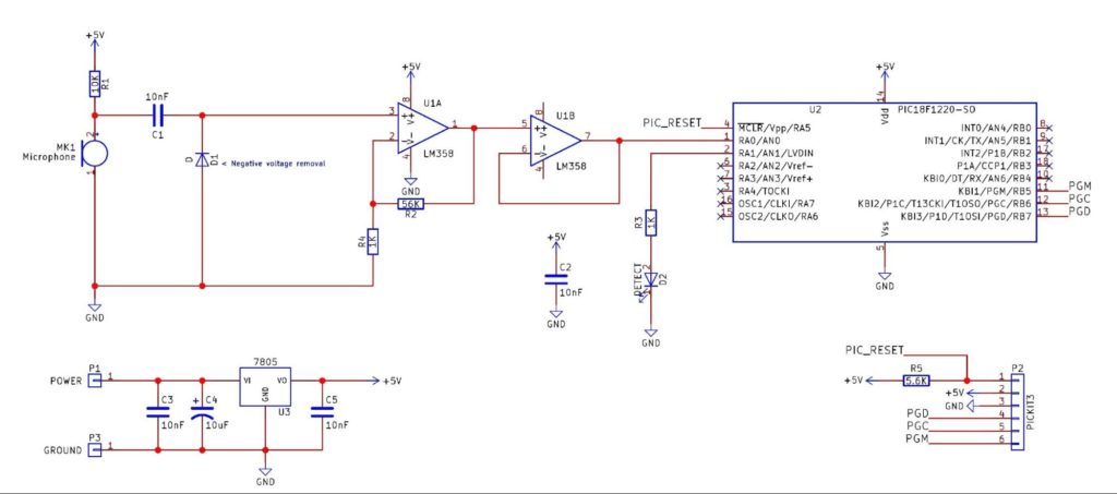
Insect Detector Schematic
How Does the Insect Detector Work?
While many potential methods exist for detecting flying insects, this circuit will take advantage of the processing power of a PIC to turn on an LED when a certain frequency is detected. Luckily for us, flies, bees, and wasps all typically generate a buzz whose frequency is between 150Hz and 250Hz which is easy for a PIC to detect.
For this circuit to work, it has two main components: the microphone amplifier and the main PIC controller. Therefore, the first task is to amplify the detected audio so that it can easily be operated on by the PIC.
Amplifying Sound with an Electret Microphone
The electret microphone produces an output that contains the audio signal but it also contains a large DC offset. This is easily removed with the capacitor, C1, but this then results in negative voltages being formed on the input of U1A. To remove these negative peaks that will form, D1 is connected between the capacitor and ground (when the capacitor becomes negative, D1 will become forward biased and thus discharge the negative voltage). This is important because the LM358 can behave unexpectedly if any of the input becomes more negative than the negative supply which is connected to 0V.
With the audio signal now only containing positive peaks, it is amplified by U1A, which is configured (thanks to R2 and R4), as a non-inverting amplifier whose gain is approximately 50 (the real value is closer to 57 but this is not important). The amplified signal is then buffered by U1B and this is then fed into AN0 which is an analog in pin on the PIC.
Detecting Frequencies With a PIC
But the real magic happens inside the PIC as it runs the detection code. The job of the PIC is to detect a frequency that lies near the frequency of a typical buzz sound from insects (between 150Hz and 250Hz) and, if this frequency is detected, turn an LED on.
The first section of code (SECTION 1) is setup code that enables TIMER0, the ADC, TMR0 interrupt, and configures the various IO pins. The second section starts the main program loop and this loop is found in most (if not all) PIC projects.
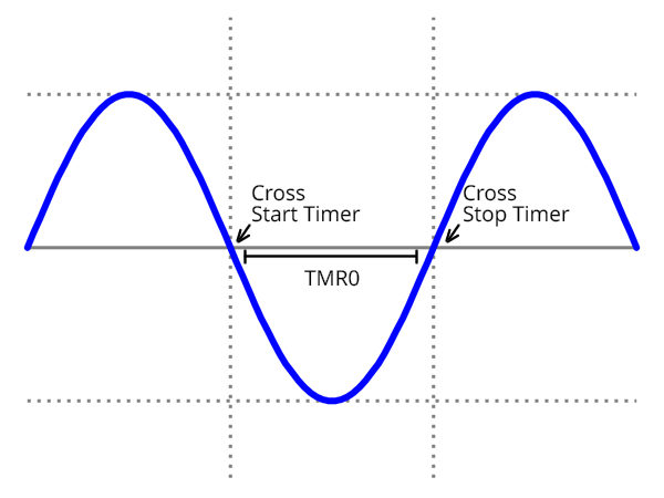
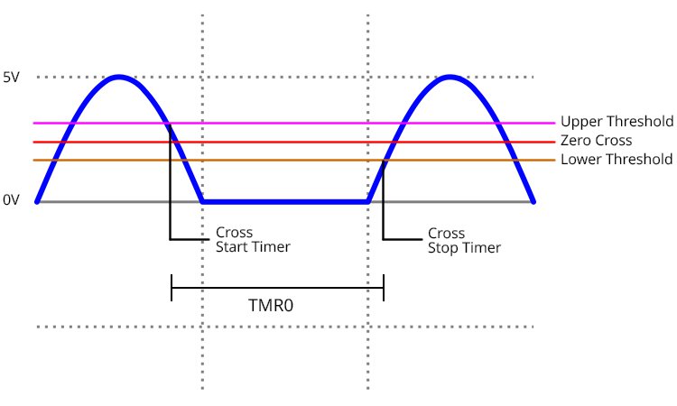
Now, to determine the frequency of the incoming audio signal may seem complex but is probably the easiest method for doing so. If you needed to measure the frequency of a sine wave on a graph, you would most likely measure the distance between one point on the waveform and the same point on the next oscillation. While this is easy with a graph, it is very difficult if all you have are instantaneous values coming in (and not enough RAM to store all these points). But if you know that the incoming waveform will repeat in a similar fashion, you can look for “zero-crossing”.
In other words, if you know that the incoming audio signals oscillate about a value then you can look to see when the incoming data crosses this point. When it does, you can start a stop watch and wait until the incoming signal crosses that point again. When it does, you stop the stop watch and immediately you can determine the frequency of the wave.
However, this would not be very practical and would be very susceptible to noise and so hysteresis is used (think Schmitt trigger) to determine if the incoming analog signal from the microphone has crossed the “middle”.
Our hysteresis has two states, low and high. If we are in the low state, then when the incoming signal goes below the low threshold, the hysteresis state will switch to the high state. When this happens, the signal now needs to cross the upper threshold for the hysteresis state to switch back to the low state.
So the main loop first starts ADC readings and waits to see if the incoming signal crosses the threshold level (which is determined by the hysteresis state). When it does, TMR0 is cleared and started which begins our measurement and we then enter a second hysteresis loop.
When the signal now crosses the other threshold level, the timer is turned off. At this point, all we have to do is check to see if the timer falls within a specific range (which corresponds to our desired frequency) and, if it does, we know that we have detected the buzz! Depending on your environment and setup, you may need to adjust the value of lowerThreshold, upperThreshold, and the range values (timerValue > 50) && (timerValue < 150) as all circuits are not made equally.
To test your circuit, it would be best to load up a tone generator on a computer with speakers and go through different frequencies until the circuit reacts. From there, you can make small adjustments until it reacts reliably to buzzing.
For practical use, you may need to increase or add amplification stages as real-life buzzing is very quiet.
Construction
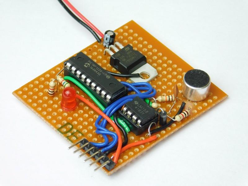
This project can be made using most circuit construction techniques thanks to the use of all through-hole parts (including the microcontroller).
Some of these circuit construction techniques include stripboard, matrix board, veroboard, solderless breadboard, and even DIY PCBs. Unfortunately, the author's CNC machine was broken at the time of this project and so no PCB files were produced. However, considering the project's simplicity and the small number of components it needs, the circuit could easily be routed on a single-sided PCB.
