This PIC gas alarm system displays detection levels and fires an alarm when a dangerous level of gas is detected.
Gases such as natural gas can be incredibly dangerous, and can even lead to death if not kept in check. In this DIY Hacking project, we will look at the MQ-2 Gas Sensor, understand how it works, and learn how to make a simple PIC alarm system that both displays the current detection levels and fires an alarm when a dangerous level of gas is detected.
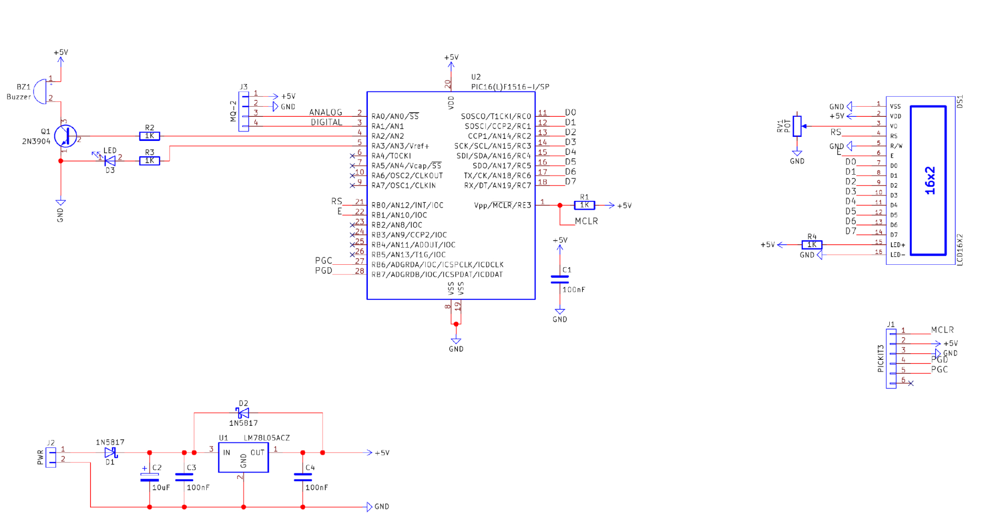
PIC-Powered Gas Alarm Schematic
How the PIC-Powered Gas Alarm Works
The two main components of this project are the MQ-2 sensor and the PIC16F1516. The MQ-2 gas sensor is capable of detecting multiple kinds of explosive gases, such as alcohol, and has high sensitivity to gases including LPG, propane, and hydrogen. At the heart of the sensor is SnO2 (tin oxide), which has a large resistance when in clean air. When the sensor comes into contact with an explosive gas, the sensor's resistance decreases. This sensor is mounted on a PCB that has a comparator circuit, so when the detection level goes beyond a limit, a signal is produced that can be read directly by a PIC (the output pin of the sensor is either 1 or 0). However, the sensor module also has an analogue output, which allows us to make measurements. So the MQ-2 sensor is connected to two pins on port A of the PIC16F1516: RA0 and RA1. RA0 handles the digital signal, which informs the PIC that the gas levels are at a dangerous level, while RA1 handles the ADC conversion, which allows us to display the detected value on an LCD.
The PIC itself runs firmware, which...
- Takes analogue readings from the sensor
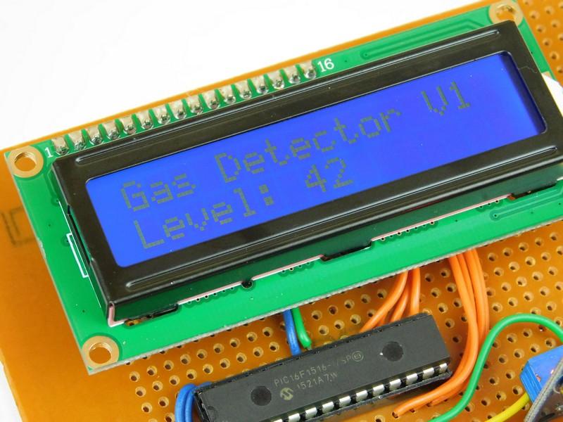
- Displays analogue values on a 16X2 LCD
- Probes RA0 for danger levels
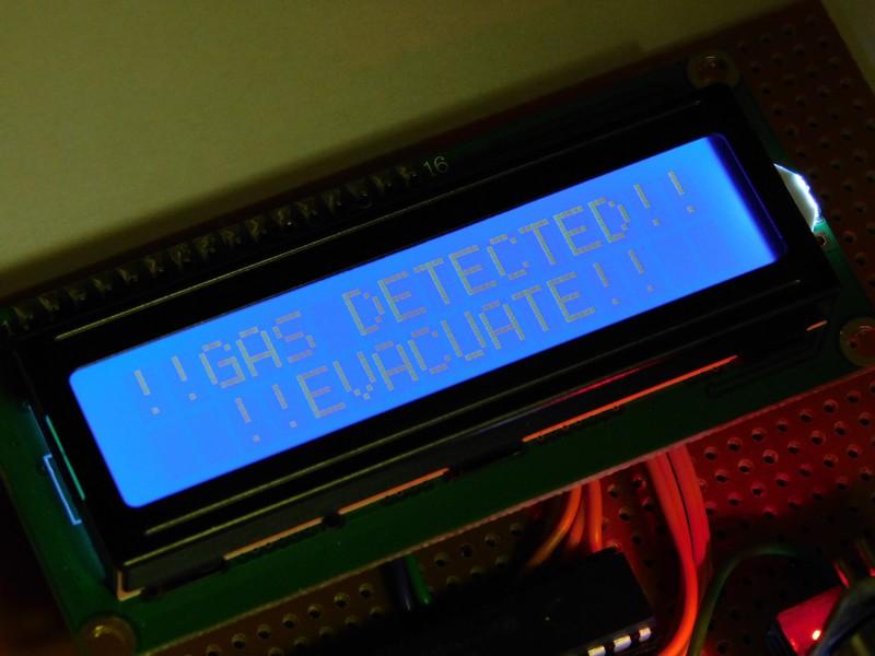
- Fires alarms and sounds buzzers
Upon starting up, the PIC runs its configuration, which configures the IO ports, ADC module, internal oscillator, and the LCD. With the system configured and running correctly, the PIC starts its infinite loop. This involves taking measurements from the sensor, displaying the results, and then checking the danger level digital output of the MQ-2 sensor. Measurements are taken by setting the GO bit in the ADC module, waiting for the conversion to finish, and then reading ADRESH. This number is then converted into an ASCII string and sent to the LCD module.
If the PIC detects that the gas level has become dangerous (thanks to the digital output of the MQ-2), it goes into an alarm routine, which turns on the buzzer and the white LED. Unlike the fire detector project, this circuit does not have a reset button or any way of getting out of the alarm loop (resetting the alarm involves disconnecting the power and re-enabling it). This is done to reduce the chance of the alarm turning off in the event of an explosive gas detection. Unlike fire and smoke, gas buildup can result in an explosion at any time, so evacuating quickly is vital.
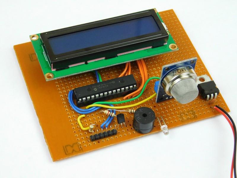
Construction
You can build this project using most circuit construction techniques, including breadboard, stripboard, matrixboard, and PCB. All the components in this project are available in through-hole packages, and due to some unforeseen circumstances, I could not get a PCB made. Therefore, I opted to use stripboard, which resulted in a rather neat-looking project!
Even though this project can detect explosive gases, it is in no way reliable enough or proven to work in all situations. This is a fun project that aims to explore sensors, so do NOT use this in an industrial environment where people's lives are dependent on the project. If you need a gas alarm, purchase a commercial one that is proven to work!
Related Articles