Turn a small PIC18 micro and an OLED display into a miniature handheld classic game console.
The video game industry is massive, bringing in an estimated $108 billion a year. But have you ever thought of making your own video game? In this DIY Hacking project, we will turn a small PIC18 micro and an OLED display into a miniature handheld classic game console.
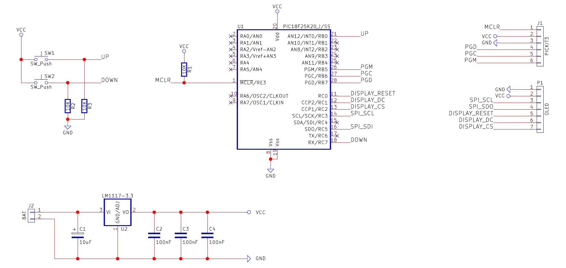
Digital Table Tennis Game Schematic
How Does the Digital Table Tennis Game Work?
The system has two sides: the hardware side and the software side. The hardware side is incredibly simple, with just a few external components. These ensure that the PIC can run properly and accept user input and power control in the form of a single AMS1117 3.3V regulator. The power supply uses 3.3V, as the OLED is a 3.3V device.
Most of the complexity in the project is found in the code that runs the table tennis game. Since the code is too extensive to describe in detail, we'll discuss the main aspects here. The program is split up into multiple functions that are either called arbitrarily or conditionally. These functions include ...
- Main loop – The main game loop
- Draw game – Draws the game
- Collision engine – Handles ball collisions
- Player movement – Handles player and CPU movements
The main loop (void main) is an infinite loop that runs the game and calls all the needed functions in the correct order. First, the loop calls all the important game functions such as player movement and collision detection, then sits in a delay loop. This delay loop prevents the game from running too fast and is a crude way to slow the game down. A better system would take advantage of timers, and on a timer overflow, the game would iterate once. Doing that would free up CPU time to do other tasks. But for now, a delay loop is used.
PlayerMove() is a function that handles all player and CPU-based movements. If the player is pressing one of the direction buttons, it will advance the player in said direction. The CPU simply tries to stay in line with the ball, so if the ball goes too far in any direction, the paddle will move in that direction until the ball is in line with the paddle. Such logic would be unbeatable if the ball's Y speed were equal to the computer's paddle Y speed. So, to get around this, the ball's Y speed has randomness introduced such that the Y speed of the ball can be greater than the Y speed of the CPU's paddle.
CollisionEngine() is a function that handles all the collision-related code to the ball. If the ball hits the top or bottom of the game area, it is simply deflected on the Y axis. If the ball hits one of the paddles, it will be deflected, but the angle and speed of this deflection is completely random. This is to add a level of difficulty to the game and to help remove predictability. The collision engine also restarts the game if the ball hits one of the sides that the player/CPU has to guard. While no point system has been introduced in this game, adding such a feature should be very easy.
The draw_game() function is responsible for displaying the ball and paddles on the screen. Its first job is to clear the screen by writing 0x00 to every block in the display, however, this is not the most efficient method for clearing a screen thats maximum operating frequency is rather limited. A more efficient method for screen clearing is to only clear areas that have been written to, which is very difficult, or store a buffer internally in the PIC of the screen and only stream it out once. However, that would require 1024 bytes of RAM, and with C18 being limited on maximum buffer sizes, such a feat is rather implausible. The next task of the draw game function is to draw the ball and paddles. The last function that draw game completes is the drawing of the lines.
Downloadable Files
Digital Table Tennis Game Files
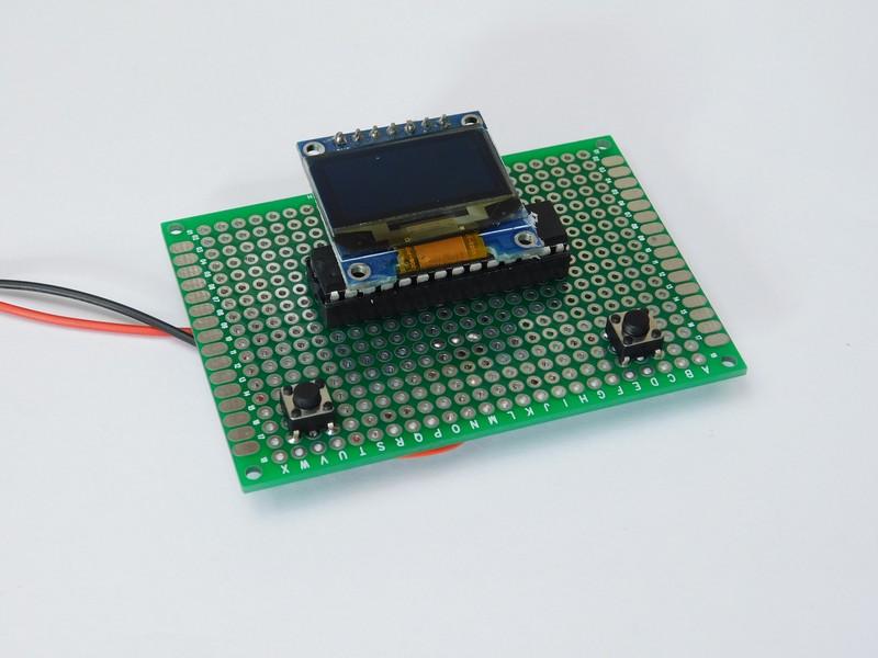
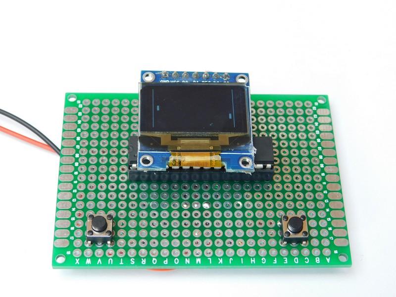
Construction
This project can be made using most circuit construction techniques, thanks to the use of all through-hole parts (including the microcontroller). Some of these circuit construction techniques include stripboard, matrix board, veroboard, solderless breadboard, and even DIY PCBs. Unfortunately, the author's CNC machine was broken at the time of this project, so no PCB files were produced. However, considering the simplicity and few components needed to make this project work, the circuit could easily be routed on a single-sided PCB.