This article focuses on explaining the DC current effect on the inductor. This will also provide the necessary informat
The inductor design in the design of the switching power supply is the many challenges for engineers. Engineers not only have to select an inductor, but also consider the current, winding resistance, mechanical dimensions, and so on. This article focuses on explaining: the DC current effect on the inductor. This will also provide the necessary information for selecting the appropriate inductor.
Understand the function of the inductor
The inductor is often understood to be an LC filter circuit in the switching power supply output (C is the output capacitor). Although this is correct, it is necessary to understand the inductor in order to understand the inductor design. Also, you can check this post to learn the function of inductors.
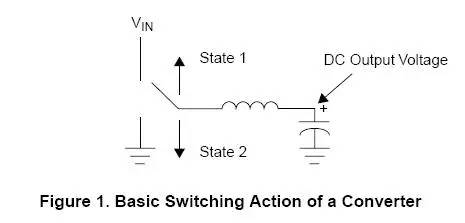
In a buck transformation (Fairchild Typical Switch Controller), one end of the inductor is connected to the DC output voltage. The other end is connected to the input voltage or GND by switching frequency.
In the process of state 1, the inductor is connected to the input voltage ("High-Side") MOSFET. In the process of state 2, the inductor is connected to the GND. Due to the use of such a controller, in two ways can be used to ground: ground or by diode or by "low-side" MOSFET. If it is a way, the converter is called "synchronus" mode.
Now consider that the current flowing over the two states is changed if it is. During state 1, one end of the inductor is connected to the input voltage and the other end is connected to the output voltage. For a buck converter, the input voltage must be higher than the output voltage, so the forward voltage drop is formed on the inductor. In contrast, in the process of state 2, the inductor of the input voltage is connected to the ground. For a buck converter, the output voltage will be a positive terminal, and therefore a negative pressure drop is formed on the inductor.
We use inductive voltage calculation formulas:
V = L (di / dt)
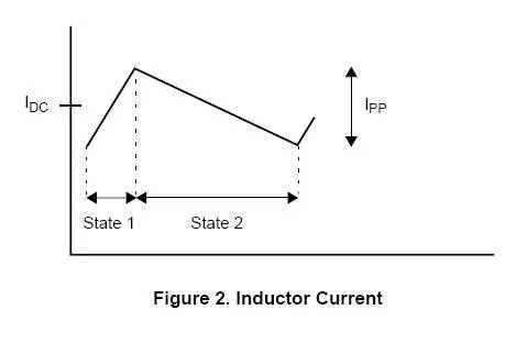
Therefore, when the voltage on the inductor is timing (state 1), the current on the inductor increases; when the voltage on the inductor is negative (state 2), the current on the inductor decreases. The current through the inductor is shown in Figure 2:
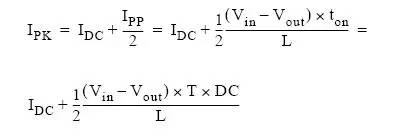
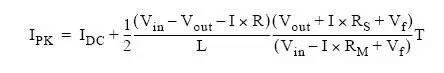
Through the figure above, we can see that the maximum current flowing through the inductor is half of the DC current plus the peak current. The above figure is also called a ripple current. According to the above formula, we can calculate the peak current:
Among them, TON is the time of state 1, T is the switching cycle (counting of the switching frequency), the DC is the duty cycle of state 1.
WARNING: The above calculation is assumed that the pressure drop contrast input and output voltage on the respective metader (the turning pressure drop on the MOSFET, the inductor direction or the positive voltage drop of the shadrous diode in the asynchronous circuit) can be Ignored.
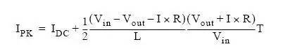
If the decenesis of the device is not negligible, it is necessary to use the following formula to accurately calculate:
Synchronous conversion circuit:
Asynchronous conversion circuit:
Among them, RS is the resistance of inductive electrical resistance resistance anti-plus inductor winding resistance. Vf is the forward voltage drop of Schottky diodes. R is RS plus MOSFET on-resistance, R = RS + RM.
Saturation of inductor magnetic core
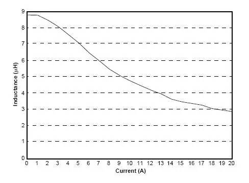
Through the inductor peak current that has been calculated, we can find what the inductor is generated. It is easy to know that as the current of the inductor increases, its inductor will decrease. This is due to the physical characteristics of the core material. The amount of inductor will decrease is very important: If the amount of inductor is reduced, the converter will not work properly. When the current of the inductor is large to the degree of inductor, the current at this time is referred to as "saturated current". This is also the basic parameters of inductor.
In fact, switching power inductor in the conversion circuit will always have a "soft" saturation. To understand this concept, you can observe the curve of the actual measured inductor VS DC current:
When the current increases to a certain degree, the amount of inductor will not drop sharply, which is called "soft" saturation characteristics. If the current increases, the inductor will be damaged.
Note: The amount of inductor will exist in many types of insects. For example: Toroids, Gapped E-Cores, etc. However, the Rod Core inductor will not have this change.
With this soft saturation, we can know why they will specify why the amount of inductor under the DC output current is specified in all converters; and because the change of the ripple current does not seriously affect the inductor. In all applications, you want the ripple current as much as possible because it affects the ripple of the output voltage. This is why everyone always cares about the inductor under the DC output current, and will ignore the inductor of the inductor under the SPEC.