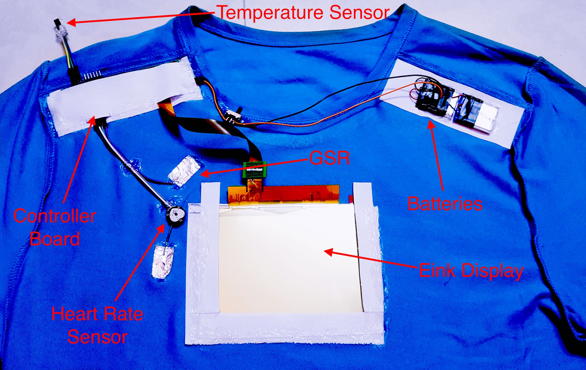
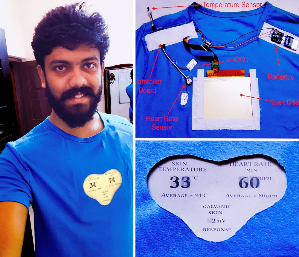
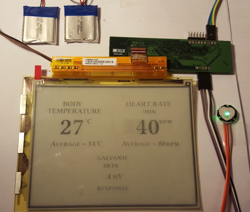
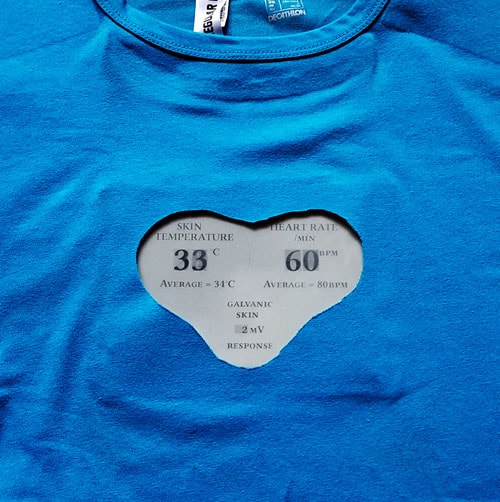
This t-shirt has an e-ink display for the wearer’s heart rate, skin temperature, and galvanic skin response.
The E-tshirt project uses human computer interaction techniques to assist the people classified as autistic by helping their caregivers understand their emotional status via their autonomic data. This open source project consists of a t-shirt embedded with an electrophoretic (eink) display that can display the wearer’s hear rate, skin temperature, and galvanic skin response. Sensors and a custom designed miniature PCB are embedded into the fabric to allow this.
The E-tshirt was made to help autistic people and their caregivers by allowing them to understand what kind of objects, sounds, colors, and situations trigger meltdowns within the person. Here is a short video of the concept:
This tutorial provides only the relevant technical information for recreating this project in order to suit your own applications and to help people in distress. All the source code and design files for this open source project can be found at the end of this page. It is recommended to read the original concept and development story before starting with this tutorial:
E-tshirt: Concept and background
E-tshirt: Technical story of Development
Prerequisite Knowledge
In order to recreate this project, it requires you to have a working knowledge for using embedded C. Platforms such as STM32 Discovery, ChibiOS, uGFX, and Eagle are used for developing this project. If you are new to these platforms, it is recommended to understand these platforms first before starting:
- STM32L152 Discovery board Reference Manual STM32L152 datasheet STM32L152 command manual
- ChibiOS embedded development environment for RTOS, HAL, etc. Reference manual Troubleshooting forum
- uGFX embedded library for integrating displays and developing GUIs. Drawing commands Gdisp
- Eagle PCB design software
These are some additional tutorials that helped during the development of E-tshirt:
- Driving an E-ink display using STM32L152
- Introduction to ChibiOS
- A quick view of ChibiStudio
- Integrating DHT11 sensor through STM32 and ChibiOS
- C pointers
- Arrow member selector operator
- Typecasting in C
- Structures in C
- Structures and pointers
- Static data type Tutorial
- Typedef Tutorial
Required Materials
All the parts and components that were sourced for this project can be found in this
document. Most of them would only be required after you have fabricated the beta/alpha prototype boards. In order to start tinkering, only the first four components would be required. Apart from these components, tools like hot air soldering station, soldering iron, tweezers, connecting wires, etc would be required.
How Does the E-tshirt Work?
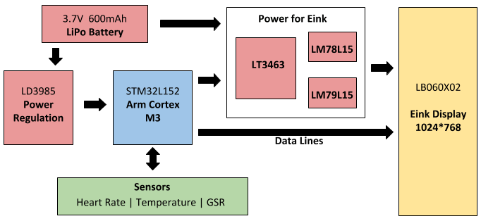
In this project, I am using parameters such as heart rate, skin temperature, and galvanic skin response to determine the user’s emotional state. Various sensors are used for achieving this. The entire system is handled by an STM32L152 microcontroller which was selected for its low power consumption. This ARM Cortex - M3 controller offers 256 KB flash memory and 32 KB RAM.
Sensors
As shown in the block diagram, three sensors are used for getting the autonomic data. Mainly, the pulse sensor that uses reflective pulse oximetry technique to determine the heart rate. Here, since the hemoglobin in the blood offers different optical properties with respect to the oxygen content in blood, we are able to distinguish between the different heart beats.
Next is the galvanic skin response sensor which is basically two electrodes placed inside the t-shirt in contact with the person’s body. Here, a 12-bit ADC in the microcontroller is capable of sensing the conductance offered by the body through the electrodes. Based on the stress levels of the person, they exhibit greater skin conductivity due to the activation of the sweat glands.
Finally we have a temperature sensor that is embedded inside the t-shirt beneath the user’s armpit that can assist in reading the body temperature.
The data obtained from these sensors are then processed by the microcontroller to generate accurate values of the autonomic data. This is then displayed through the e-ink display.
E-ink Display
The 6 inch E-ink display used here is a thin and flexible panel on a plastic substrate manufactured by LG, the LB060X02. The display was sourced from China. The driver for the display was created for STM32L152 using uGFX platform and a miniature four layer PCB was designed to accommodate its power handling circuitry.
Power Circuitry
In this project, the system uses a 3.7V 600mAh Lithium Polymer battery that powers the microcontroller and the E-ink display. As shown in the block diagram, the LD3985 provides the 3.3V power required for powering the STM32L152 controller. The E-ink display requires a range of voltages for driving it because of the FETs inside them. It requires +22V,-20V,+15V and -15V for powering it. These voltages are produced by the onboard circuitry.
The LT3463 takes power from the battery and produces +22V (GVDD) and -20V (GVEE) based on the VPOS_CTRL and VNEG_CTRL signals coming from the controller. The +22V is then fed to the LM78L15 to generate +15V (VPOS) and the -20V is fed to the LM79L15 to generate the -15V (VNEG). LM358 is also used to produce a common voltage (VCOM) from VPOS and VNEG that is fed to the E-ink display as well.
Installing ChibiOS, GCC, openOCD and uGFX
ChibiOS is an embedded development environment for RTOS, HAL, etc. It can be considered to be a lightweight operating system for a range of microcontrollers like those from STM32. It allows us to use a standard set of commands for inter-compatibility with all these different controllers. You can follow this tutorial for installing ChibiOS:
ChibiOS Mac Tutorial
ChibiOS Tutorial for Other OS's
After installing ChibiOS and setting up the GCC (for compiling the C projects), openOCD (debugger used for deploying the hex code onto the microcontroller) by following the tutorial above, we can proceed to install uGFX.
Testing the Blink Program on STM32 Discovery Board
We can first try to run a blink program on the discovery board using ChibiOS to ensure that all the packages have been installed and setup correctly. You can do this by first importing a demo project from ChibiStudio. Go to File->Import->Existing Projects into Workspace->ChibiOS->demos->RT-STM32L152-DISCOVERY. This project consists of a demo code for testing all the modules on the discovery board like LCD, RAM, etc. You can try uploading this program later to check the different modules. Now, edit the lines within the while loop in the main program (main.c) to add the blink code for the LED:
while (true) {
    palSetPad(GPIOB, GPIOB_LED4);
   chThdSleepMilliseconds(500);
   palClearPad(GPIOB, GPIOB_LED4);
   chThdSleepMilliseconds(500);
 }
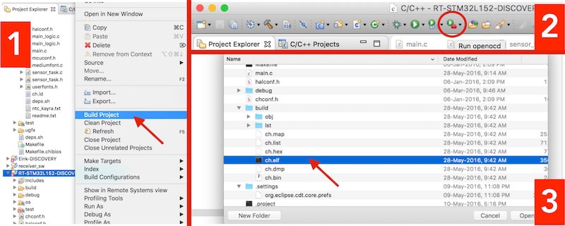
GPIOB_LED4 is the LED on the bottom right labeled as LD4 on the discovery board. This is the LED that will be blinking. To upload this program, do the following:
- Save the project (ctrl+s).
- Right click on the project and build the project.
- Click on run openocd button on the top toolbar.
- Browse and select the new file created in the build folder inside the project folder with the extension as .elf. Example: ch.elf
Once you finish uploading you should see that the LD4 LED is blinking. If it is not, try going through the previous steps and checking your install. You can also try asking in the ChibiOS forum.
Note: If you want to try setting/clearing other GPIO pins, you will have to edit the board.h file and change the pin configurations for that respective pin inside it.
Uploading the E-tshirt Code
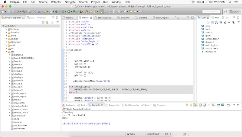
Once you are comfortable with using chibiOS, we can move to importing the code for the E-tshirt project. The code consists of the drivers for the LB060X02 eink display and the sensors. You can download it from here: E-tshirt project. Try importing this project through chibi studio and building the project. Keep editing or adding libraries based on the errors you get. You can always google the errors to get the solution or ask in the chibiOS forum.
If the project gets built successfully without errors, then we can move to the next step.
Connecting the Sensors
Next, try connecting the sensors: heart rate, GSR and skin temperature. I shall explain each in detail:
Heart Rate
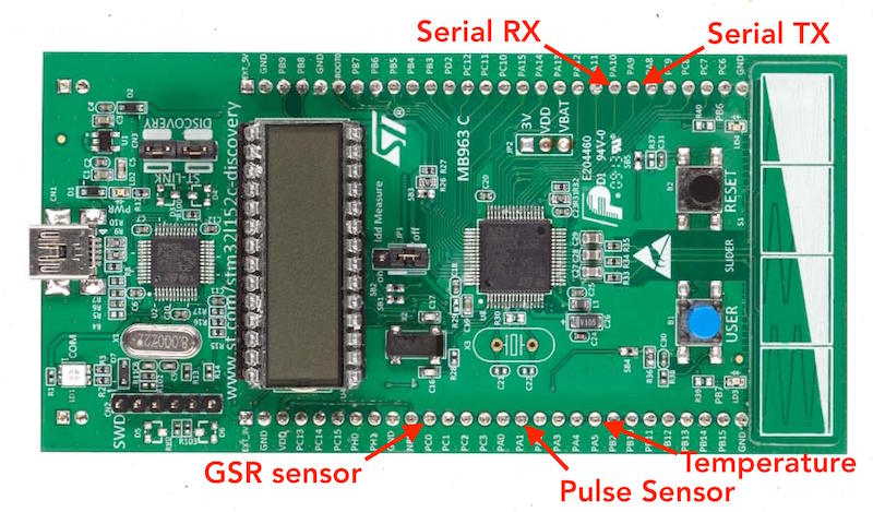
To detect the heart rate of the wearer using the E-tshirt, I am using the pulse sensor. It uses reflective pulse oximetry technique to detect the pulse. It is based on the fact that the haemoglobin in the blood offers different optical properties depending on the oxygen content of the blood. This sensor works on 3V and is connected to the PA1 pin on the discovery board (Port A, pin 1).
Note: You would have to remove the LCD on the discovery board, as several of the GPIO pins are connected to it.
GSR (Galvanic Skin Response)
The GSR of the body is basically the skin conductance. Our sweat glands open up when we are in situations of stress and hence increases the skin conductivity. We can measure this skin conductivity using the 12-bit ADC on our STM32L152. Connect the PC0 (Port C, pin 0) pin to a long connecting wire attached to an electrode. This electrode needs to be placed on the skin to be able to sense the conductivity. We need to provide a 3V line via an electrode to the area near the first electrode as well.
Skin Temperature
To detect skin temperature, I am using the LM35. When placed in contact with our skin, it can detect the skin temperature using this formula: temp = (3.0 * analogRead(tempPin) * 100.0) / 1024;
The signal line from LM35 is connected to PA5 (Port A, pin 5).
Note: All the pin definitions can be seen in the board.h file (src->board.h).
Upload the E-tshirt code and uncomment lines inside each TestThread() in the sensor_task.c file to view the data from the sensors on the serial monitor. For example, in TestThread2() for getting the ADC values from LM35 temperature sensor, you will see a commented line for:
//test_println("");
//test_printn(temp);
Uncomment those lines and save, build the project. Next connect your Serial to USB adapter to PA9 (TX) and PA10 (RX) pins on the discovery board. You can now view the data from the sensor on your serial monitor (I use the arduino’s serial monitor) after you upload the edited code onto your discovery board. Make sure you have a common ground between the Serial to USB adapter and the discovery board. You can do this procedure for each sensor to check if they are connected and working properly.
Designing the Electronic T-Shirt PCB
Beta Board
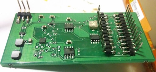
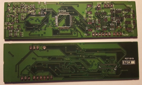
For this project, I had designed and made two different PCB boards. The first board or the Beta board was made to test the eink display. This two layer board only had the power circuitry required for driving the eink display. And connected the data lines for the eink display from the STM32L152 discovery board to the Beta board. You will anyway need a breakout board to connect to the 39 pins on the eink display, so you can download the schematic and board file for making this two layer PCB and fabricate it. I had my boards fabricated from PCB power, you can then use this board to test the eink display and verify that the code is working properly. Solder the components onto this board and test it out.
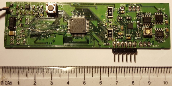
This is the final four layer PCB board that consists of the STM32L152 controller and all the power circuitry required for driving the E-tshirt. This board will be embedded onto the tshirt along with the sensors. The minimum trace width for these boards are 0.007 inch/7mils and via size diameter of 0.002 inch, drill of 0.015 inch. You will need a hot air blower to solder the parts onto this board.
Download the Eagle board design files for both the boards from here: E-tshirt PCB designs and the component list.
Tips for Soldering
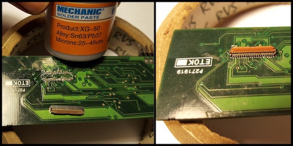
Use liquid flux for soldering these parts, apply solder paste (mechanic paste) only in case the solder on the board is not enough. Use heat resistant Kapton tape to prevent soldered parts from overheating. Soldering the 39 pin FPC connector could be a challenge since the connector will start melting unless you remove the plastic flap on the top of it. The next challenge would be soldering the STM32L152 controller, as you need to evenly heat all the pins. Also make sure that all the pins of the DFN10 package for LT3463 is properly soldered, as it's a no leads package.
Take proper caution to wash your hands in case you touch the solder paste, as it contains lead.
Uploading the E-Tshirt Code to the Board
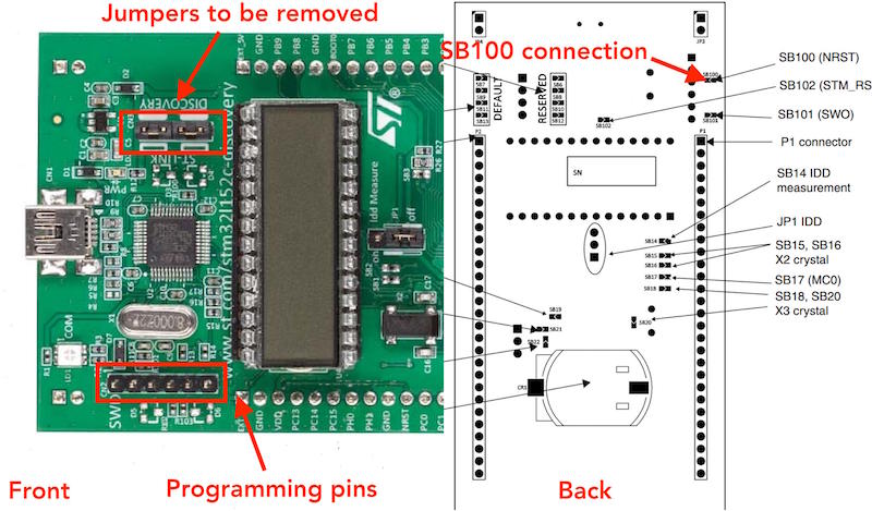
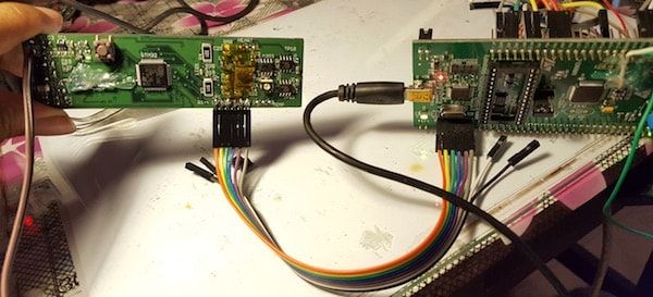
After fabricating the board, test it out with the E-ink display. To do that, upload the code to the board via the programming pins on it. Connect the T_JTCK, T_JTMS, T_NRST, CL and T_SWO pins (refer the eagle schematics) on the board to the respective pins on the CN2 connector on the discovery board. Make sure you remove the jumpers on the CN3 connectors on the discovery board and also desolder the SB100 connection for accessing the NRST pin on your E-tshirt board. Now upload the code to the board. You can use a power supply or battery that provides 3.8-4V 600mAh for powering the system.
For testing the beta board, you have to connect all the data lines from the Discovery board to the connector on the beta board. You can refer to the schematic of the beta board and the board.h file from the E-tshirt source code to understand which pin is which.
Embedding the System Onto the T-Shirt
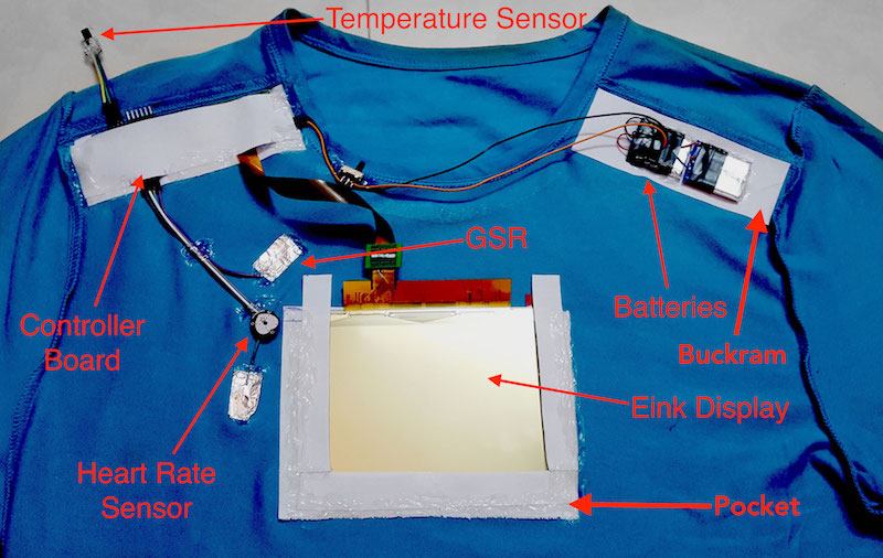
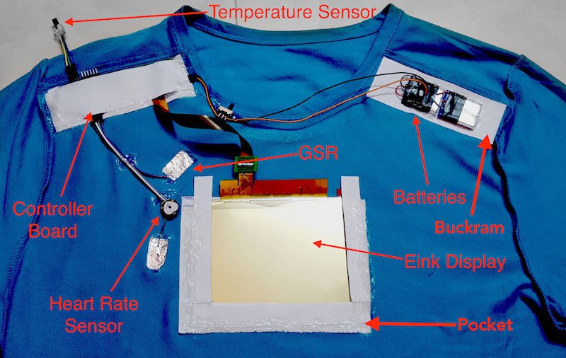
You can improvise to create your own technique to attach the system onto the t-shirt or you can check out my method. First, you would have to make a hole on the t-shirt, through which the eink screen would be visible. For doing this, I have ironed a stiff cloth called buckram onto the back of the t-shirt. This cloth sticks to the t-shirt after it gets heated and makes it stiff. This will let you cut the t-shirt easily as the fabric does not tend to curl up or bend.
I also used the same material to create pockets for holding the eink display and the controller board. This lets you remove those components so that you can wash the-shirt later. Hot glue is also another good adhesive that can be used to keep the parts in place.
Resources for the Electronic T-Shirt Project
Source code Beta board design files
Alpha board design files
Technical story of Development
E-tshirt concept and background
This project was supported by a lot of people and I would like to thank each one of them. I would like to start by thanking Dr.Neena Shilen (Developmental Pediatrics, Sunrise Hospital) for giving me valuable guidance in designing this project. And also wish to express my gratitude to Mr.Anirudh Sharma (MIT Media Lab, Graviky Labs) and Mr.Sijo Kuruvilla George for their valuable insight and counsel. I would also like to thank Mrs.Ancy Paulose, Mr.Antony Aby and Mr.Loui Paulose from Foxglove Graphics for assisting with the textile seaming and darning. And finally Dr.Sanjeev S and Dr.Usha Rani (Rtd. Scientists at CIFT) for their invaluable support. The work done by Mr.Petteri Aimonen (Author, Essential Scrap) on driving an E-ink display has greatly supported this open-source project.
