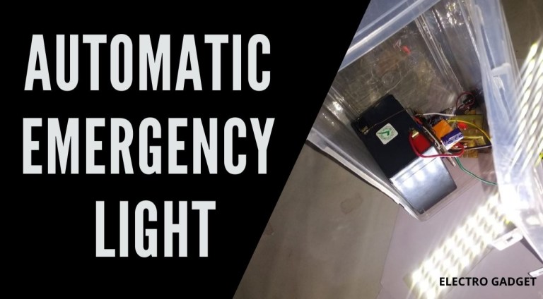
This low-cost automatic emergency lighting circuit turns on a lamp during power failures.
An Automatic LED Emergency Light circuit is designed to turn ON when there is no adequate lighting or if the power supply is cut-off. Earlier fluorescent lights were used to build such circuits. But the use of LEDs has proven to provide adequate lighting for a longer period before draining the battery.
Circuit Explanation
The voltage from the step-down transformer is rectified by diode D1 and filtered by C1. The NiCad battery gets charged with about 100 mA via the diode D2 and resistor R1. The battery must have a capacity of at least 2 Ah to tolerate the charging rate.
When the main power supply fails during a blackout, the charging current is interrupted and a current flows from the base of T1 via resistor R2 which triggers the transistor to conduct and the two emergency lamps light up. When the main power returns, the charging current flows again through D2 and the transistor turns the lamps off.
The “TEST” button S1 is used to check the function of the circuit. If the secondary coil of the transformer delivers a higher voltage level, replace R1 with a higher value resistor to avoid exceeding the maximum charging current allowed for the NiCad battery being used.


