Design an NMOS amplifier with following specifications.
Given specs: AV = 50 and VDD = 12 V, Rin is of MΩ order.
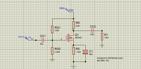
Single stage common source amplifier
In electronics, a common-source amplifier is one of three basic single-stage field-effect transistor (FET) amplifier topologies, typically used as a voltage or transconductance amplifier. The remaining terminal is what is known as "common". In this example, the signal enters the gate, and exits the drain. The only terminal remaining is the source. This is a common-source FET circuit. As a voltage amplifier, input voltage modulates the current flowing through the FET, changing the voltage across the output resistance according to Ohm's law. However, the FET device's output resistance typically is not high enough for a reasonable. The common source circuit provides a medium input and output impedance levels. Both current and voltage gain can be described as medium, but the output is the inverse of the input, i.e. 180° phase change. This provides a good overall performance and as such it is often thought of as the most widely used configuration.
Design process of an NMOS amplifier
NMOS amplifier with following specifications
AV = 50 | VDD = 12 V | Rin is of MΩ order |
|---|
100 KΩ load
| 2N7000 MOSFET | lowest frequency (20 Hz) |
Step 1 : kn calculation
From Datasheet of 2N7000, VGS,off = 2 V (VTh) , VGS,on = 10 V and ID,on = 1 A
Then, ?? = (2??,??) /(?????−??ℎ)^2 gives kn = (2 * 1 A)/(10 -2)^2 = 0.03125 A/V^2
Step 2: Q-point calculation
???? = (???/??)+ ??ℎ = 12/50 + 2 = 2.24 V
???=12?'?(????−??ℎ)2= 0.5 *0.03125 *(2.24 – 2)^2 = 0.0009A
Step 3: Choosing Bias resistors
??=(0.5*???)/??? = 0.5 * 12 / 0.0009 = 6.67 KΩ. I choose RD as 6.8 KΩ (standard value)
??=??/5 = 6.67/5 = 1.35 KΩ. I choose RS as 1.5 KΩ (standard value)
Rin is of MΩ and Rin = R1 || R2 and R1 > R2,
Let R2 = 2.2 MΩ.
??=????+ ??=????+?????=?2?1+ ?2 ×???
2.24 V + 0.0009 A * 1.5 K = 2.2 ??1+ 2.2 ? ×12
2.24 + 1.35 = 2.2 ??1+ 2.2 ? ×12
R1 = 4. 68 MΩ.
I choose R1 as 4.7 MΩ (standard value)
Step 4: Choosing Capacitors for fmin = 20 Hz
?c1 ≥1/(0.2? ∗???? ∗ ???)=1/0.2? ∗???? ∗ (?1 || ?2)
Cc1 ≥1/(0.2? ∗20 ∗ (4.7∗2.2)/(4.7+2.2) M)
Cc1 ≥ 53.13 nF
I choose CC1 as 68 nF (standard value)
?c2 ≥1/{0.2? ∗???? ∗ ???)=1/(0.2? ∗???? ∗ (??+??)}
Cc2 ≥1/{0.2? ∗20 ∗ (6.8 + 100) ?}
Cc2 ≥ 745.49 nF
I choose Cc2 as 820 nF (standard value)
?? ≥1/{0.2? ∗???? ∗ ???=10.2? ∗???? ∗ ??}
?s ≥1/{0.2? ∗20 ∗ 1.5 ?}
Cs ≥ 53078.56 nF = 53.078 uF
I choose Cs as 68 uF (standard value)
Component
2N7000 type MOSFET | 12v Supply | RG1 = 4.68M |
|---|
?? = 6.8k | Rs = 1.5k | RG2 =2.2M |
Cc1 = 68nF | Cc2 = 820nF | Cs = 68uF |
Designed by Md.Nahidul Islam