This project describes the design of a sun tracking algorithm using
Dialog's GreenPAK IC.
This project describes the design of a Sun Tracking algorithm using Dialog's IC for capturing the maximum amount of energy from the Sun by keeping our panel at the most optimum orientation.
Below we described steps needed to understand how the solution has been programmed to create a 2-axis solar sun tracker. However, if you just want to get the result of programming, download GreenPAK™ software to view the already completed GreenPAK Design File. Plug the GreenPAK Development Kit to your computer and hit the program to design the solution.
Introduction
This project describes the design of a Sun Tracking Solar Panel System using a Dialog GreenPAK IC. The use of Solar Energy has seen widespread use over the last few years. It is hence only logical to find new ways in which the energy of the sun can be harvested in as great a quantity as possible. The use of a system that tracks the movement of the sun to capture maximum intensity at all times is the next step towards greater energy production.
The SLG46880 IC will work as the brain of the system managing the events of the actuation of motors to control the position of the Solar Panel. It will use Light Dependent resistors to monitor the sun and actuate motors accordingly.
Dialog products are suitable for this purpose for the following reasons:
- The smaller size of the whole system would mean less hassle to accommodate the sensor along the whole apparatus.
- In a system that has to be powered by solar energy, keeping the power consumption to a minimum level is of utmost importance. Here the product will excel as it consumes a very small amount of power while performing the required tasks. Also, Wake/Sleep function for the comparators will also ensure minimum power utilization when required.
- Programming Dialog products is by far the easiest and least time-consuming part of the whole project design process. Anyone with basic electronic engineering knowledge can program the IC to perform many basic as well as complex tasks. This is one of the biggest advantages over other solutions as rapid prototyping and project execution can be achieved fairly easily using Dialog’s GreenPAK IC products.
As we all know, the usage of Solar Energy systems has seen a widespread increase over the last few years. Solar panels that are mounted to be stationary can have their efficiency compromised when the sun moves away to a less-optimal angle. This can be compensated by installing Sun trackers that move to track the maximum intensity of light. Hence, a solar panel system equipped with a tracking system produces more power throughout the day. One can say that Sun tracking systems can become essential and ubiquitous as more development continues.
Design Components
For this application Dialog’s SLG46880 IC has been employed along with the following components:
Light Dependent Resistors
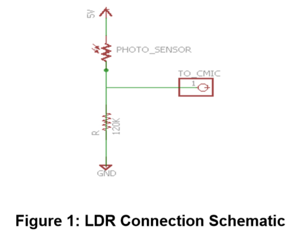
For the detection of light intensity, Light Dependent Resistors (LDRs GL5516) have been used. LDRs are very robust, sensitive, and can change their resistance with slight changes of light intensity. These little sensors can be found in both complex and simple applications based on the detection of light. Two LDRs have been used to detect the intensity of light in our project.
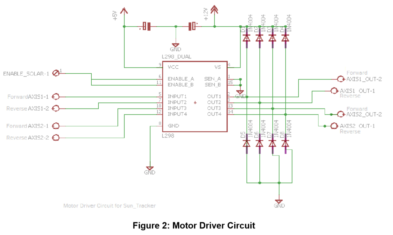
An L298d motor driver has been used to drive the motors that align a solar panel in accordance with sensor readings. Since the IC cannot handle larger current output, the use of a motor driver was essential. This driver can control the direction of two motors simultaneously, with the max current draw set at 3 Amperes at 12 volts. This motor driver replaces 4 transistors that would otherwise be used to control the direction of a single motor. Since two motors are required for our project, the replacement of 8 components with a single integrated component not only saves unnecessary complexity but also reduces power requirements for the project.
The solar panel itself is used to sense ambient light. A solar panel yields a full output in direct sunlight, and no output without any light. These conditions can then be converted to produce appropriate levels to a digital input pin of the IC. By using a simple voltage divider circuit, the 18 V generated by the solar panel used for this project can be level-shifted down to become a 3.3 V signal that will represent a High-Level logic input for the SLG46880 IC.
For this project, small permanent magnet DC motors have been employed in the design that can handle and move a small solar panel easily, with a limited current draw to decrease power consumption. The speed of the motor will not affect the system's capability to track.
GreenPAK Design
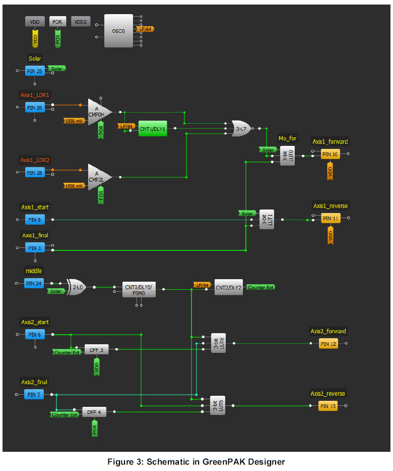
Due to the size of the design, the application has been broken into smaller subsets. This design is for a dual axis system, which can completely track the motion of the sun. Let’s look at the circuit design for the first axis which tracks the movement of the sun as it goes from East to West.
Within the design, there are two LDRs dedicated to tracking the movement of the sun as it goes from east to west. As the sun angles away, it results in a change to the amount of light sensed by the LDR, lowering the output voltage below the threshold which has been set at 1056 mV. As soon as the sensed value becomes lower than this threshold, a digital LOW (0) is generated by the comparator. A Delay block has been incorporated in the design to filter out any false noise readings. The outputs of the Comparator and the Delay block are then fed to a NOR Gate. This gate only gives a Digital LOW when all three inputs are LOW. This block is necessary for the completion of the filter. The second LDR is used for a little more precision within the design.
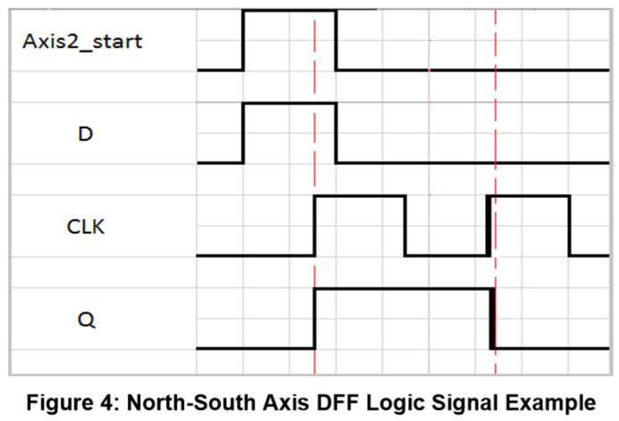
The actuation of the motor in the forward direction is governed using the Look UP Table as described in Figure 4, where:
IN0 = Output from Axis1’s final position sensor.
IN1 = Output from the photo sensors.
IN2 = Ambient Light sensing using the Solar Panel.
As can be seen in the table, the actuation of the motor is only achieved when both sensors detect a change in the presence of the sun and the final position has not been reached.
Looking at the design we can also see that the actuation of the motor in the reverse direction has also been incorporated to bring the panel back to its starting position to catch the sun when it rises in the morning. This actuation is also governed by a 3-bit Look-Up Table (LUT) which is described in the following figure.
Here the inputs are:
IN0: Position sensor sensing the final position of the solar panel.
IN1: Position sensor sensing the starting position of the solar panel.
IN2: Ambient daylight sensing using the Solar panel.
According to the design, the reverse actuation of the panel is achieved only when the final position is reached at the end of the day and only when the sunlight has faded so much that the Solar Panel doesn't register it. The reverse actuation also stays HIGH when all inputs are zero because this reverse movement will completely move the panel to its starting position. During that transition, the position sensors will not give a reading. As soon as the panel reaches its starting position the reverse motion will be stopped.
The sun moves from the east in the morning towards the west in the evening, but the sun also moves slightly in the north and south directions. Hence if we want to capture the sun completely, the tracking algorithm should also track this movement. Research suggests that the sun moves from north to south very slightly and the change in angle is about 23.5 degrees within a span of 4 months [1: https://physics.weber.edu/schroeder/ua/sunandseasons.html]. Hence, we can design an algorithm that may account for this fact and only actuates the motor only every 4 months in order to save unnecessary power consumption compared to changing just a fractional degree per day.
For tracking the movement of the sun in the north and south space a counter has been used which counts for around 122 days (approximately 4 months). The value of the counter is increased as soon as the sun goes down and the solar panel stops registering sunlight and produces a zero output.
But since we have to have three orientations in different seasons just like the sun which also cycles through three main positions throughout the year, this situation requires the use of memory which will remember the previous direction of motion and continue in the same direction to reach the next desired position.
For accomplishing this task, D-Flip Flops have been used. When the system is at its starting position marked by the position sensor as soon as the counter reaches its set value, the system will move towards the middle position. As soon as the apparatus reaches the middle position the counter will be reset, and a new countdown will begin. In order to track the sun's motion, the system needs to move in the same direction as it moved the last time to reach the final position.
The DFFs used to fulfill this purpose by staying high for one more cycle as they tend to keep their previous value when the clock signal falls and hence moving the motor in the forward direction as designed using the Look-up tables. The same algorithm is also implemented to bring the system to its initial position from the final position while avoiding any clash between forward and reverse cycles.
To summarize, the forward actuation will only be achieved if:
– The counter has finished its required amount of counting.
– The system was at its starting position or was at its starting position in the previous cycle.
A similar pattern is followed for reverse actuation.
The amount of actuation required to achieve a rotation of 23.5 degrees every 4 months can be set using the three-position sensors feeding into Axi2_start, Middle, and Axis2_final.
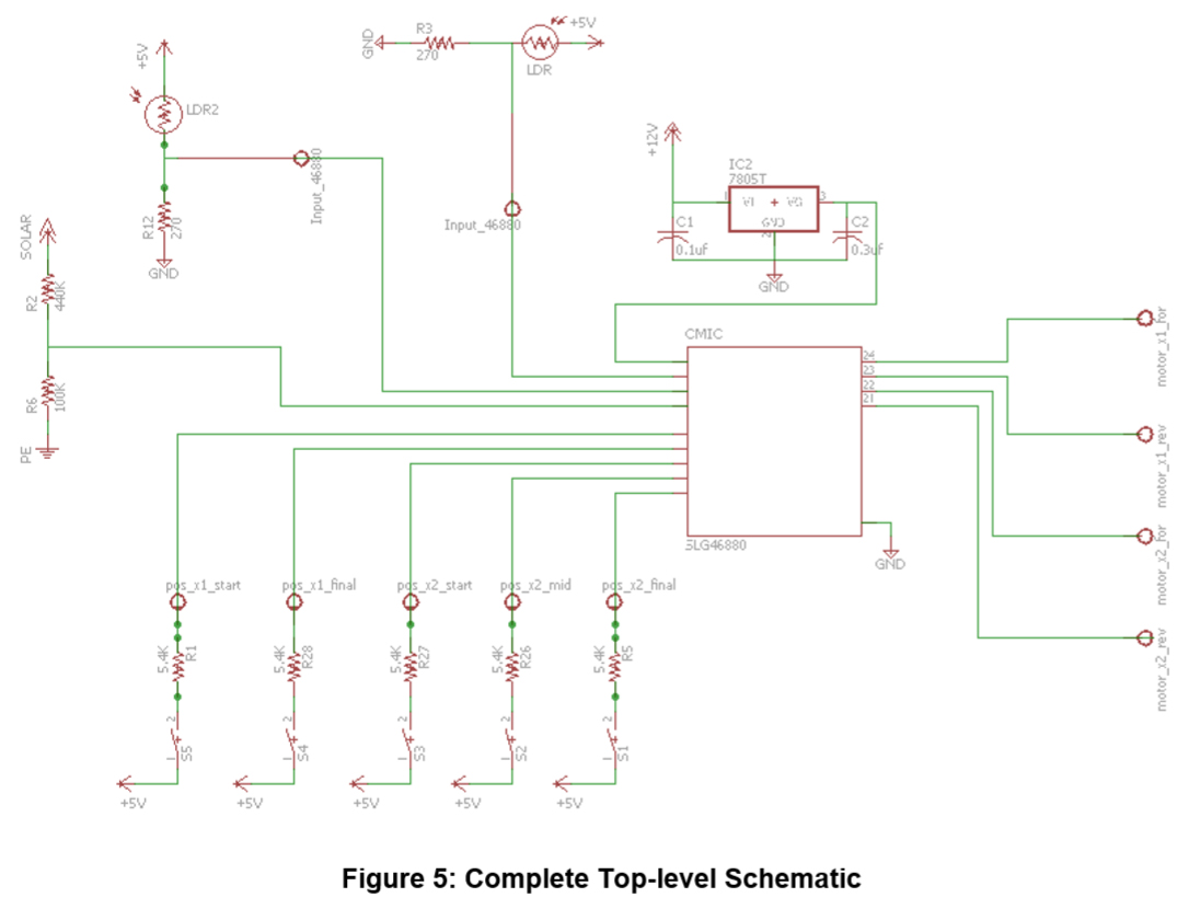
Complete Schematic Details
The following figure shows the complete schematic designed for this project.
Following is a brief description of the different inputs going into the IC.
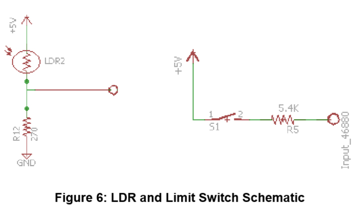
A voltage divider is used to bring down the output level of the LDR to a level that is suitable for the IC to measure and then take action.
Contact Switches as Position Sensors
Contact switches are required to sense the starting and the final position of the Solar Panel. They require very little circuitry but play an important role in the overall design of the system.
Results
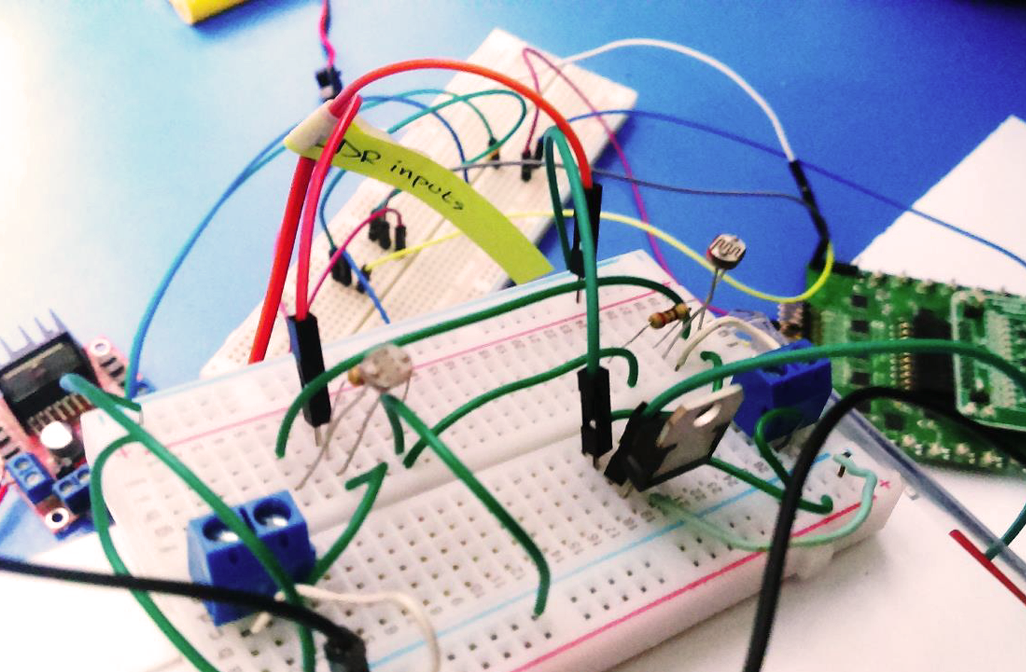
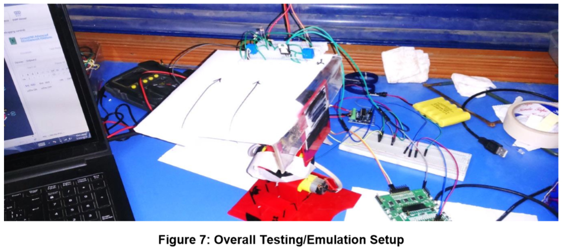
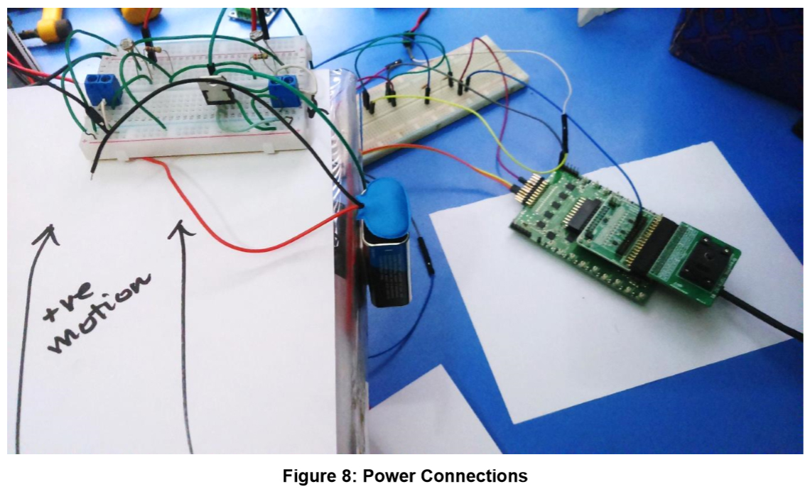
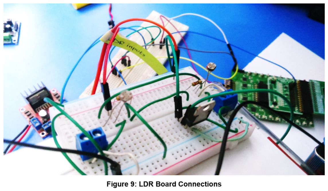
After the design was complete and each component of the system was independently tested, all of the components were connected to each other as mentioned in the above circuit. The IC was connected using the Universal Development board along with the socket.
The design was then tested by putting the board into Emulation mode present within the designing software and then was tested using a bright source of light (a 100 W Incandescent bulb) for possible outcomes of the system. The IC performed well for the design and the whole system was able to follow the source of light as intended. The counter's working for counting the number of days was also tested in emulation using a Hot Key to represent the sunsets. The following are a few pictures of the testing setup.
Conclusion
For this project, a Sun tracking system for maximizing solar panel efficiency was proposed. This was successfully achieved using the SLG46880 IC. Further improvements such as Wake/Sleep control of the IC during the night time may be implemented in the system to further reduce power draw from the whole system for maximum efficiency.