Build an LTE-connected GPS tracker for your drone using the Particle Boron LTE and an Adafruit Ultimate GPS FeatherWing.
Here is an issue that you might encounter if you are into flying quadcopters or other autonomous aerial vehicles, especially using FPV technology: you are flying your drone, possibly around obstacles, through terrain, past trees, and your drone crashes.
What if you don't remember exactly where your quadcopter crashed? This is especially an issue if you are flying with FPV goggles that make it very easy to lose track of where your drone is flying relative to your position. Your drone might crash in the tall grass or land in a tree or bush. All of these scenarios are disappointing, considering that drones can be expensive investments.
So, in this project, we will build an LTE-connected GPS tracker that can be fitted to your quadcopter. With this tool, you will be able to locate your crashed or missing drone straight from your smartphone in the field. Plus, since battery power is a valuable commodity on RC aircraft, we will build the system so that it can be toggled ON and OFF from your transmitter. This way, the GPS locator will not use any power until you need it to find your lost aircraft.
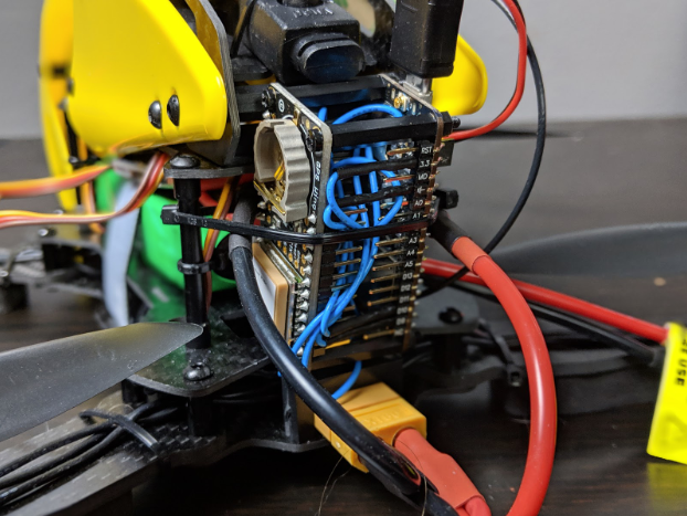
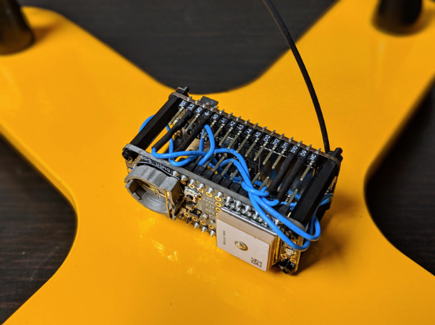
The GPS tracker mounted on a drone.
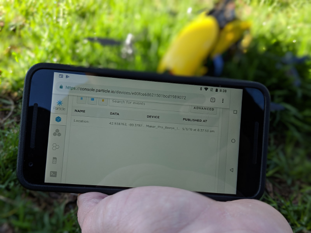
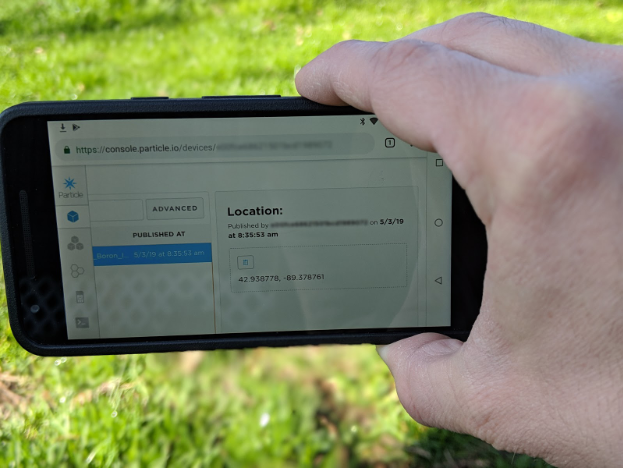
Tracking the drone using the Particle.io console.
Required Hardware
- Particle Boron LTE
- Adafruit Ultimate GPS FeatherWing
- UBEC Step-Down Converter
- Receiver-controlled switch
- Male USB connector
- M2 nylon standoff kit
About the Adafruit Ultimate GPS FeatherWing
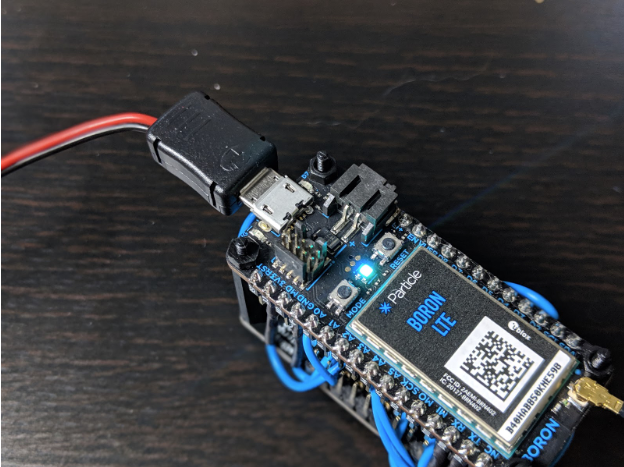
At the heart of this project are two development boards, the Particle Boron LTE, and the Adafruit Ultimate GPS FeatherWing. The Particle Boron is covered in greater detail in a different article, but before we start building our drone GPS locator, it will be useful to understand how the Ultimate GPS FeatherWing works.
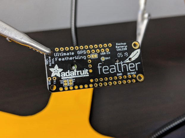
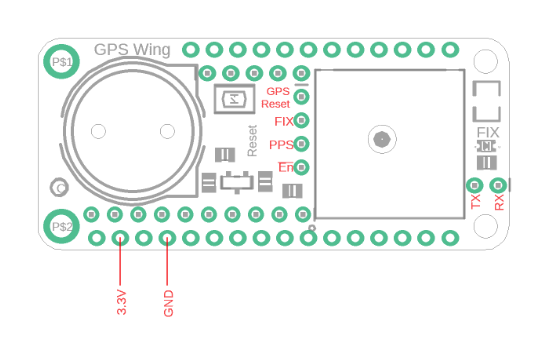
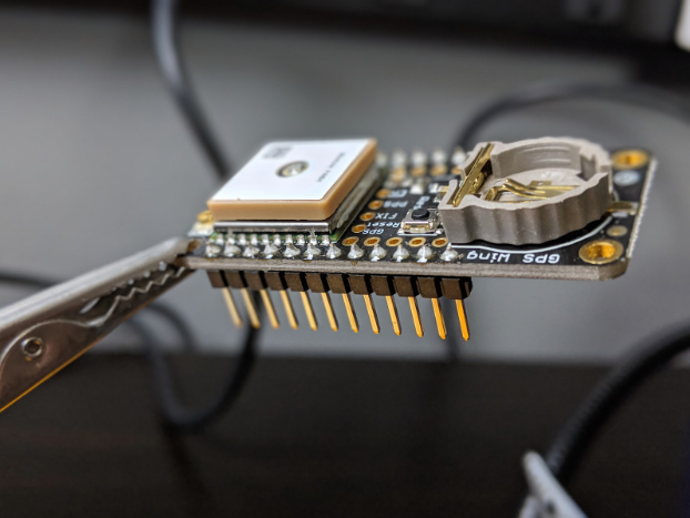
The Adafruit Ultimate GPS FeatherWing
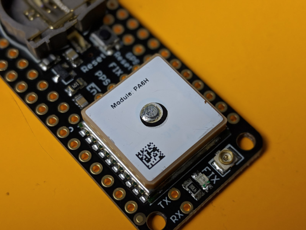
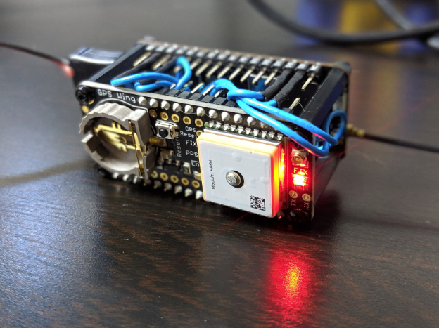
The first major functional part of the GPS FeatherWing is the GPS module itself, which is the square part on one end of the board. This is an MTK3339 GPS receiver, a high-sensitivity chipset capable of tracking up to 22 GPS satellites and update its location up to ten times per second.
Furthermore, and this is important for our project, the unit draws very little current, only about 20mA while tracking. This is important because electrical energy from the battery can be in short supply on drones.
The second major part of the board is the real-time clock (RTC) system. We will not be using the RTC for this project, but it is an extremely useful tool for data logging applications. The RTC is powered by a coin cell battery that can be optionally inserted into the holder on the opposite side of the board from the GPS module.
Finally, the board has several pins broken out that will allow power to be delivered to the board and allow the Particle Boron to obtain information from the GPS module. Also, the reason the FeatherWing was chosen for this project is because the mounting holes coincidentally match up with the mounting holes on the Particle Boron.
GPS module mounting holes.
Powering the System
The second concept to understand before we start building the drone GPS tracker is how the battery power used to run the aircraft will be controlled to power the Particle Boron and the Ultimate GPS FeatherWing.
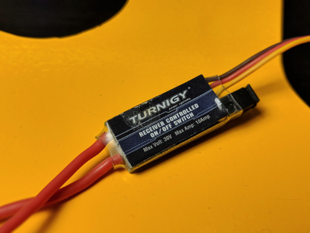
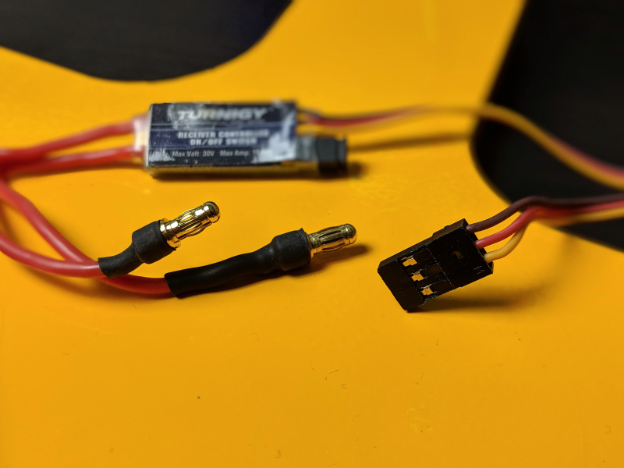
The first task is to turn the GPS unit ON and OFF so that the system does not consume any battery power until it is needed. We will use a receiver-controlled switch for this purpose. This accessory connects to the radio receiver onboard the drone and can be toggled ON and OFF using the receiver’s AUX output. This kind of accessory is commonly used to turn LED lights ON and OFF, but we will use it to activate the GPS tracker when we need to locate the drone.
Turnigy receiver controller ON/OFF switch
Second, a typical quadcopter runs off a battery that supplies between 7.4V and 22.2V. This is far too high to power the Particle Boron, which accepts a 5V input through the USB port (which will then be regulated down to 3.3V by the onboard linear voltage regulator).
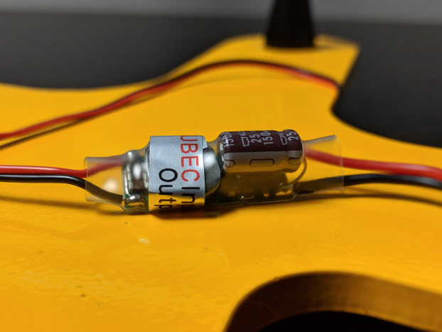
So, the second part of the power system for this project is the DC/DC step down converter used to output 5V from the battery. The part, called a universal battery eliminator circuit (UBEC) is common on RC planes and quadcopters for running 5V accessories, like LED lights, off the battery. For this project, it will serve as a 5V power supply for the GPS system.
The universal batter eliminator circuit (UBEC).
Building the Drone GPS Tracker
Now that we have some background into the major parts of the drone GPS tracker, we can start building the system. We will start by piecing together the power system and then connect the Ultimate GPS FeatherWing to the Particle Boron.
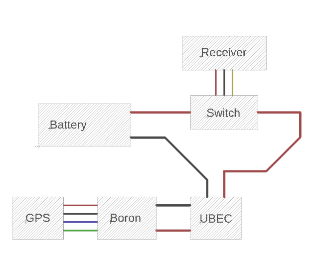
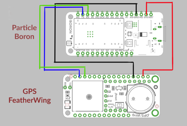
The wiring diagram below shows the rough placement of each part within the design. More details about the connections between the GPS module and the Boron will be provided later on.
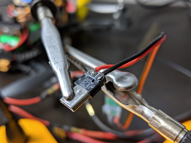
Attach the Receiver-Controlled Switch to the Battery
The first step is to connect the receiver-controlled switch to the quadcopter’s battery. Depending upon the design of your aircraft, you might already have a power distribution board or a splitter used to connect the battery to multiple systems onboard the drone.
The receiver-controlled switch has two input wires and a three-wire header.
The receiver-controlled switch.
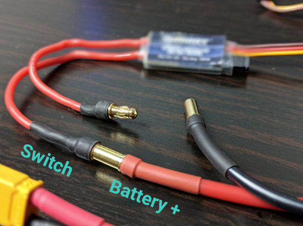
The wires that connect to the battery are thicker than the header wires, which connect to the radio receiver. First, connect one of the thicker wires to the positive (red) wire from the battery. For now we will leave the other thick wire disconnected.
Connecting the switch to the battery.
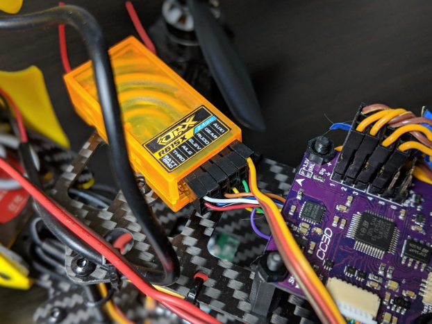
Next, the three-wire header will connect to the radio receiver. Most radio receivers have an AUX connection, which is sometimes simply the highest numbered connection.
You will need to observe the correct polarity for the connection between the receiver-controlled switch and the receiver itself. The black wire from the switch is ground and the yellow wire is for a signal.
The connection between the receiver-controlled switch and the receiver.
Add the UBEC to the Circuit
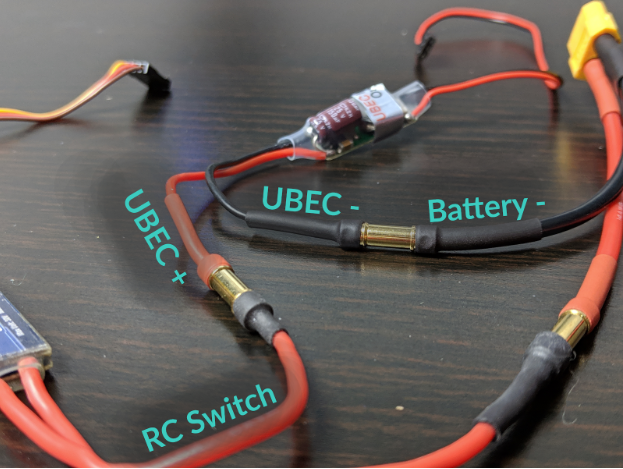
With the switch in place, the next part to add to the design is the UBEC. Right now there are two free connections in the power system, one from the receiver-controlled switch, and the second from the negative terminal on the battery. The UBEC has a set of wires on each side. The side without a header connects to the battery and switch. Simply connect the black wire to the negative terminal from the battery and the red wire to the receiver-controlled switch.
Adding the UBEC to the circuit.
Wire the Particle Boron to the Adafruit Ultimate GPS FeatherWing
Now that we’ve finished assembling the power delivery system for our drone GPS tracker, we will switch gears slightly and assemble the business end of the system by wiring the Particle Boron to the GPS FeatherWing.
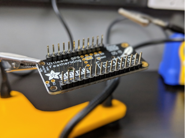
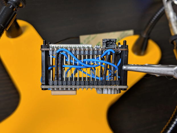
The first step is to wire headers to the Adafruit Ultimate GPS FeatherWing so that we will be able to plug in header cables. The GPS FeatherWing includes a set of male breakaway headers in the correct lengths. One detail you will notice on the GPS FeatherWing is that there are two rows of pins on either side of the board. We will be using the outside set of pins for this project. Simply solder the headers onto the board like you’ve probably done with other breakout boards in the past.
Plug in header cables to GPS FeatherWing.
Soldering the header pins.
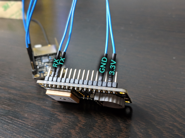
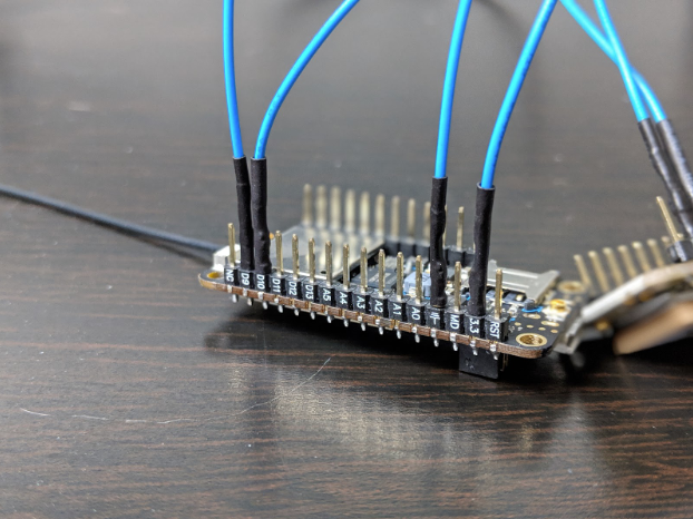
With the headers in place, we can wire the two boards together using jumper cables. Because we will be mounting the assembly onto the drone, where free space is limited, we will be using 6-inch jumper cables. In the next section, we will package the GPS tracker assembly into a tidy little bundle that will fit on the drone.
Connections between the Particle Boron and the GPS FeatherWing.
Connections |
Particle Boron | Ultimate GPS FeatherWing |
3.3 V | 3.3 V |
GND | GND |
TX (D9) | RX |
RX (D10) | TX |
Assemble the GPS Tracker
Now that we have the Particle Boron and the Ultimate GPS FeatherWing wired together, we will attach the two boards together mechanically.
One reason the FeatherWing was chosen for this project is because it shares the same mounting hole spacing as the Particle Boron. We will use nylon standoffs to attach the two boards together.
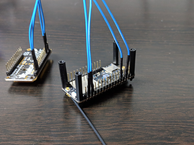
First, connect a 20mm long standoff to each of the four mounting holes on the Particle Boron.
Connecting a 20mm long standoff.
Then, mount the Ultimate GPS FeatherWing onto the standoffs. While you are placing the GPS board on the standoffs, you should be able to tuck all the wires between the boards to create a compact module.
Mount the Ultimate GPS FeatherWing onto the standoffs.
Tuck all the wires between the boards to create a compact module.
Connect Power to the Particle Boron
At this point we have a mechanism to deliver a 5V supply off the drone battery that can be switched ON and OFF from your radio transmitter. The next step is to connect power to the Particle Boron. The Boron incorporates a powerful microcontroller that will communicate with the GPS module and interpret the data. The Boron also has an onboard LTE cellular modem and includes and antenna that will enable the drone GPS tracker to send information about its location to your phone even without WiFi.
The next step in assembling the project is to connect the Particle Boron to the UBEC for power. However, we cannot connect the UBEC directly to the power input pins on the Boron because those pins accept 3.3V, not 5V. Therefore, we will connect the UBEC to the USB port on the Boron. The USB port feeds power into a linear voltage regulator that will convert the 5V supply from the UBEC to 3.3V.
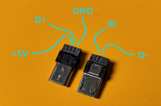
So, to get the UBEC to connect to the Particle Boron, we will first need to assemble the USB plug. The plug comes in three parts: the connector itself with solder pins on the back, plus two halves of the plastic shroud for the connector. In this case, we only need connections for power to the USB plug; we can ignore the data pins. There are a total of five pins on the USB connector, two on one side of the plug and three on the other. The 5V and GND pins are highlighted in the image below.
To assemble the connector, first solder the black wire from the UBEC to the GND pin on the USB plug and the red wire from the UBEC to the +5V pin on the USB plug.
Connect black from UBEC to GND and red from UBEC to +5V.
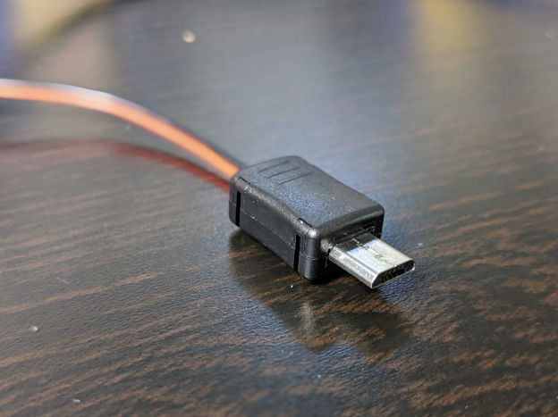
After soldering the wires onto the plug, snap the two halves of the plastic housing around the plug.
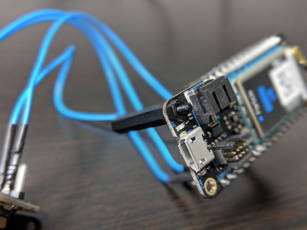
Finally, with the battery plugged into your drone’s power system, and the AUX switch on the transmitter set to on, you can test the system by plugging the USB connector into the Particle Boron. If the system works correctly, you should see two different LEDs illuminate. There is an LED on the Particle Boron that will illuminate in different colors depending upon the status of the board. The Ultimate GPS FeatherWing will also have a red LED on one side. To test the boards and make sure both are powered, simply look for these two LEDs.
Turning ON the Particle Boron.
Powering the Ultimate GPS FeatherWing.
Flash the Firmware
Now that we are finished building the hardware for this project, the final phase is to flash the firmware onto the Particle Boron that will allow the system to operate. Before flashing firmware onto the Boron, you will first need to set up a Particle account (if you don’t already have one) and claim the board. These steps are covered in detail in a previous article.
Once you are finished setting up the Particle account and claiming the board, navigate to the Particle IDE. You can copy/paste the code the code below into the IDE.
// Drone GPS Tracker with LTE Connectivity
// Author:  Scott Hatfield (aka Toglefritz)
// Published on Maker Pro

/*
DESCRIPTION:
  This sketch for the Particle Boron runs a GPS tracker intended for use
  on a quadcopter or other similar drone. The Boron has a cellular LTE
  connection allowing it to publish GPS coordinates, obtained from a
  GPS unit, to the Particle Cloud.

LICENSE:
  This code is licensed under a Creative Commons Attribution-NonCommercial-ShareAlike 4.0 International License.
  < https://creativecommons.org/licenses/by-nc-sa/4.0/ >

PARTS:
  * Particle Boron: < https://www.sparkfun.com/products/15069 >
  * Adafruit Ultimate GPS FeatherWing:  < https://www.adafruit.com/product/3133 >
  * UBEC Step-Down Converter:  < https://www.adafruit.com/product/1385 >

HARDWARE CONNECTIONS:
  * Boron GND --> GPS GND
  * Boron 3.3V --> GPS 3.3V
  * Boron D10 --> GPS TX
  * Boron D9 --> GPS RX
*/

// Add the Adafruit GPS library
#include <Adafruit_GPS.h>

// Name the Serial port
#define GPSSerial Serial1

// Connect to the GPS on the hardware port
Adafruit_GPS GPS(&GPSSerial);

uint32_t timer = millis();


void setup() {
  // Publish a little welcome message
  Particle.publish("Drone GPS tracker online");

  // 9600 NMEA is the default baud rate for Adafruit MTK GPS's- some use 4800
  GPS.begin(9600);

  // Turn on RMC (recommended minimum) and GGA (fix data) including altitude
  GPS.sendCommand(PMTK_SET_NMEA_OUTPUT_RMCGGA);

  // Set the update rate
  GPS.sendCommand(PMTK_SET_NMEA_UPDATE_1HZ); // 1 Hz update rate

  // Request updates on antenna status, comment out to keep quiet
  GPS.sendCommand(PGCMD_ANTENNA);

  delay(1000);
}

void loop()
{
  // Read data from the GPS
  char c = GPS.read();

  // If a sentence is received, we can check the checksum, parse it...
  if (GPS.newNMEAreceived()) {
    if (!GPS.parse(GPS.lastNMEA())) // This also sets the newNMEAreceived() flag to false
      return; // we can fail to parse a sentence in which case we should just wait for another
  }
  // if millis() or timer wraps around, we'll just reset it
  if (timer > millis()) timer = millis();

  // Approximately every one minute or so, print out the current stats
  // Since the drone will not be moving, we do not need to update its location
  // too often
  // Note that this statement also causes the first reading to take place
  // one minute after the Boron powers on, which gives the GPS sensor time
  // to obtain a fix
  if (millis() - timer > 60000) {
    timer = millis(); // Reset the timer

    // Check if the GPS has a fix
    if (GPS.fix) {
      Particle.publish("Location: ", String(GPS.latitudeDegrees) + ", " + String(GPS.longitudeDegrees));   // Publish the physical location of the drone
                                                                                                    // Divide by 60 to convert minutes to degrees
    }

    else {
      Particle.publish("No GPS fix");
    }
  }
}
The code is fairly simple thanks to Adafruit’s excellent GPS library which does most of the heavy lifting when it comes to communicating with the GPS module and interpreting the GPS data the module returns.
The code starts by configuring a few options for the GPS functionality, including baud rate, the information the GPS will obtain, and the rate at which the GPS unit will update its location. Most of the hard work is done by one line GPS.parse(GPS.lastNMEA()). The GPS sensor delivers NMEA sentences to the Particle Boron that look something like this:
$GPBWC,220516,5130.02,N,00046.34,W,213.8,T,218.0,M,0004.6,N,EGLM*11
One of the most useful parts of the Adafruit GPS library is the availability of functions for parsing this information, that is, getting human-readable information from the raw data delivered by the GPS sensor. Once the information is parsed, the Boron will publish the GPS location, using latitude and longitude, to the Particle Cloud once per minute.
Using the GPS Tracker
With your drone powered on (the battery connected to the power delivery system), you can activate the Particle Boron-powered GPS tracker by flipping the AUX switch on your transmitter to ON. Then, open the Particle Console. You should see your Particle Boron online.
When you select the Boron, you will start receiving events in the Particle Console. The events will be called Location, and the data in the events will be the GPS coordinates of the drone in degrees.
Opening the Particle console.
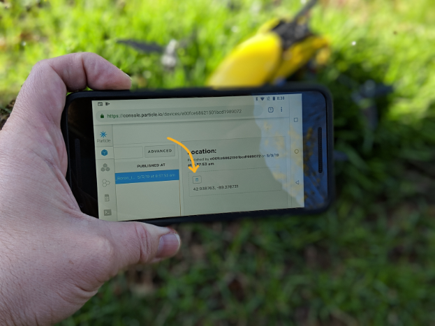
With this information, you will be able to find your lost drone by comparing the location of the GPS tracker to the location of your phone. In the Particle Console, above the GPS coordinates, there is a convenient button to copy the coordinates into your clipboard.
Copy the coordinates into your clipboard.
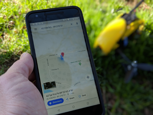
You can then paste the data into Google Maps to see the location of your lost drone on a map. You can even get walking, driving, or biking directions from your location to your drone just like you normally would when navigating with Google Maps.
Navigating with Google Maps.