Half-wave Rectifier, Full-wave Rectifier, Bridge Rectifier
In fact, a very primitive project that will interest novice electronics engineers.
Half-wave Rectifier
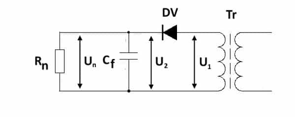
The circuit for the half-wave rectifier uses a single diode to allow only either the positive or negative half cycle of the AC input voltage to flow. The other half of the AC cycle is dropped. A capacitor is then placed across the output terminals such that the capacitor charges when there is current flowing from the input and supplies power to the load (discharges) during the half cycle that current is not flowing from the input.
To view the half-wave rectifier circuit diagram, click
Full-wave Rectifier
The circuit for the full-wave rectifier uses two diodes to allow both half-cycles (positive and negative) of the AC input voltage to flow through the circuit. Like the half-wave rectifier, a capacitor is placed across the output terminals such that the capacitor supplies (discharges) as much voltage as possible whenever the input cycle is on its downhill stage, thereby, providing close to constant positive dc voltage to the load. Notice that the two diodes are connected to the center of secondary coil of the transformer, hence, the term center-tapped transformer.
To view the full-wave-rectifier-circuit-diagram, click
Bridge Rectifier
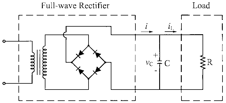
The circuit for the bridge rectifier uses four diodes. It functions similar to the full-wave rectifier except that the requirement to use a center-tapped transformer is eliminated. Again, the circuit allows both half-cycles (positive and negative) of the AC input voltage to flow through the circuit. One big difference between this circuit and full-wave rectifier circuit is that that the former is a lot more efficient. Unlike, the half- or full-wave rectifiers, the bridge rectifier does not drop half of the AC input cycle.


