This tutorial article is based on how to design a 3D upper body in SelfCAD
In this tutorial article, we are going to 3D design the upper body. The 3D modelling software that we are using is SelfCAD. The tools of SelfCAD that we will utilize are the 3D Shapes, Edge Selection, Polygon Selection, Move Tool, Scale Tool, etc. We will begin by 3D designing a cube and developing it.
You can also check one of our other articles on the site on how to design a 3D lower body for completion.
So, lets get started!
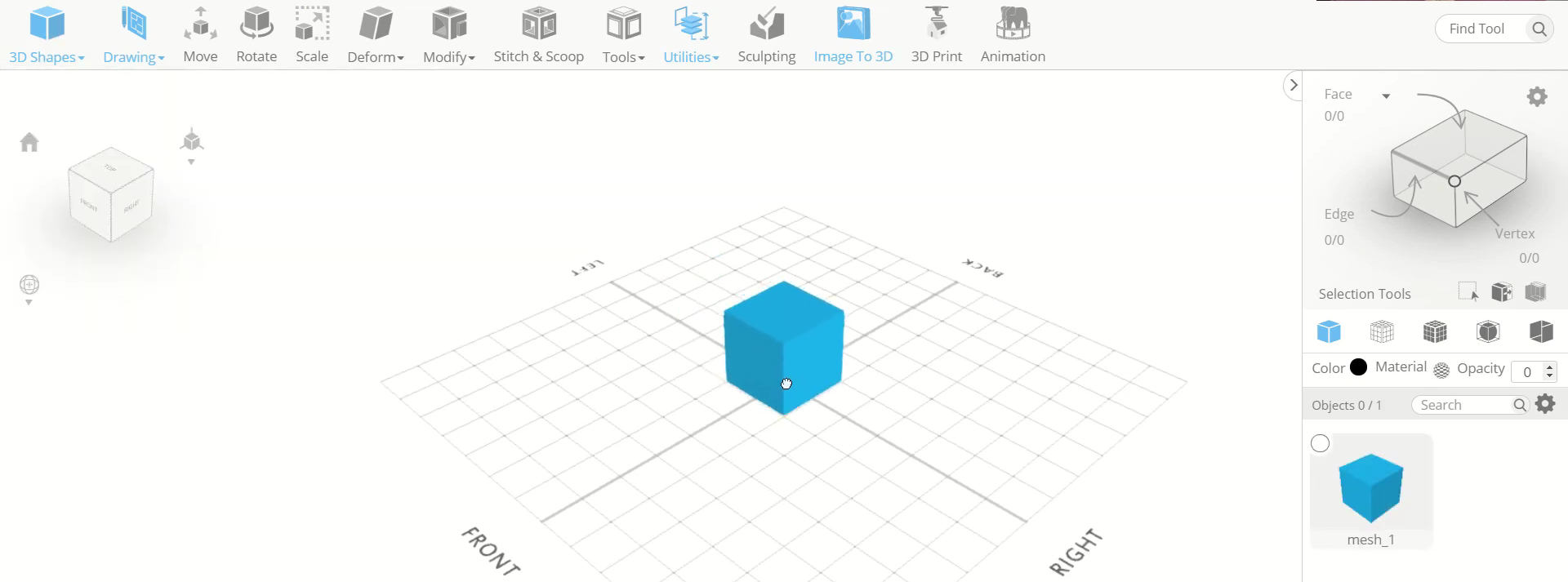
Step1:Add a cube on the working interface
First of all, go to 3D shapes and insert a cube on the working interface. Set to front view and orthographic projection. Then change to mesh+wireframe view.
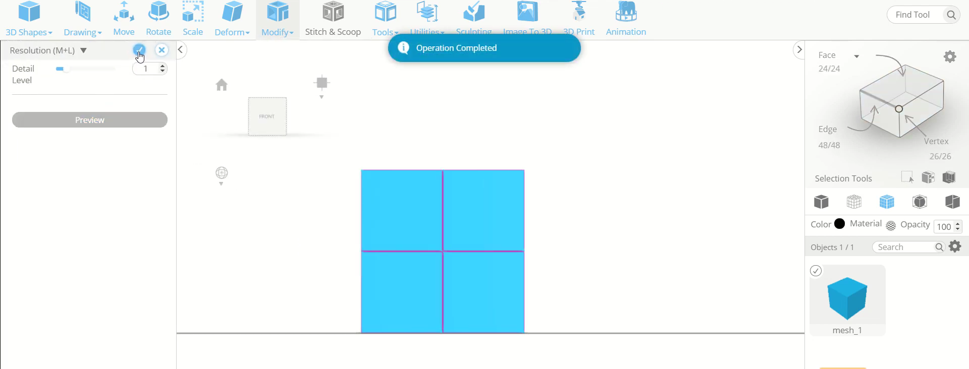
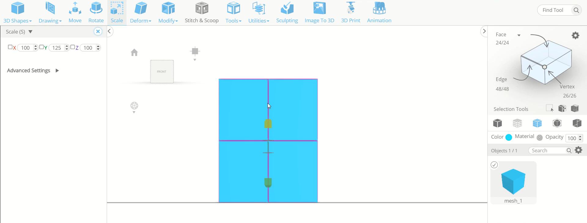
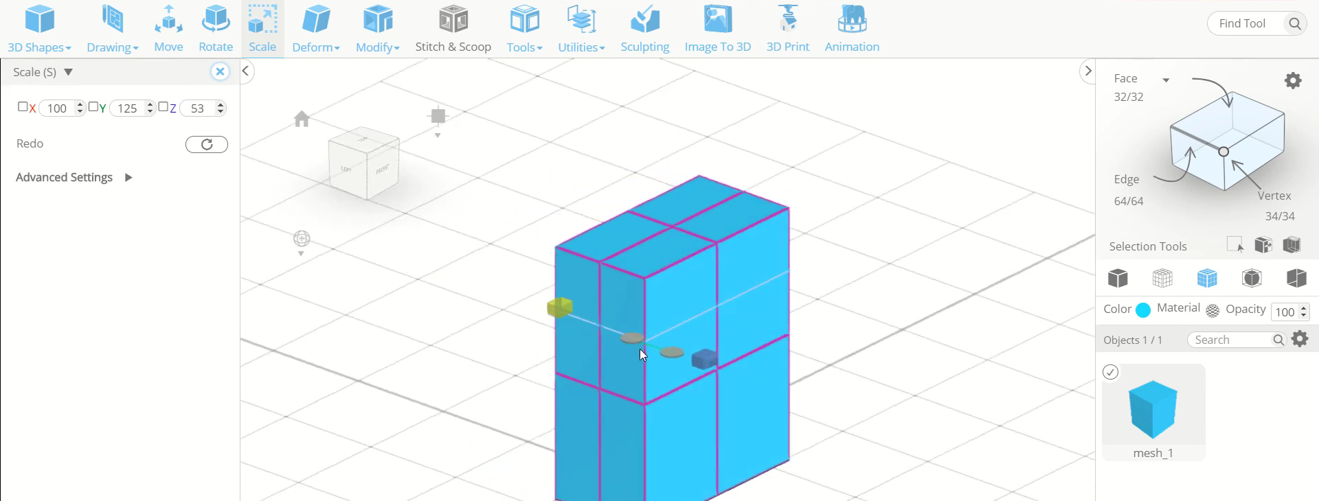
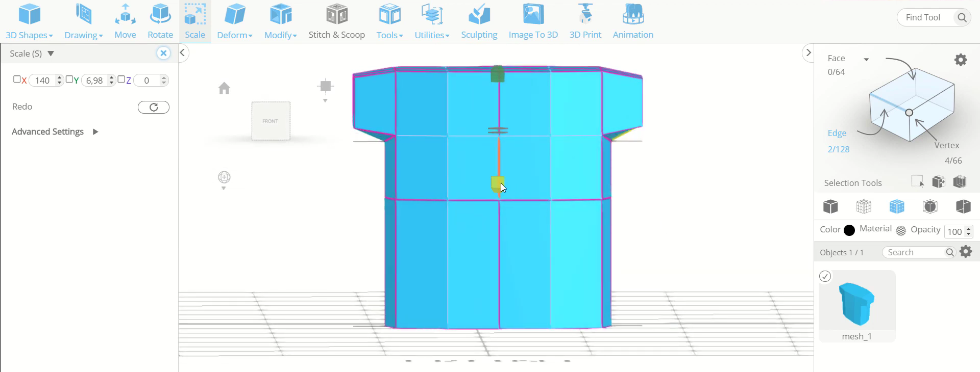
Step2: Add details and scale it towards the up
Next, go to modify and select the resolution tool. Set the details level to 1. Then use the scale tool to scale the object along the green axis towards the up.
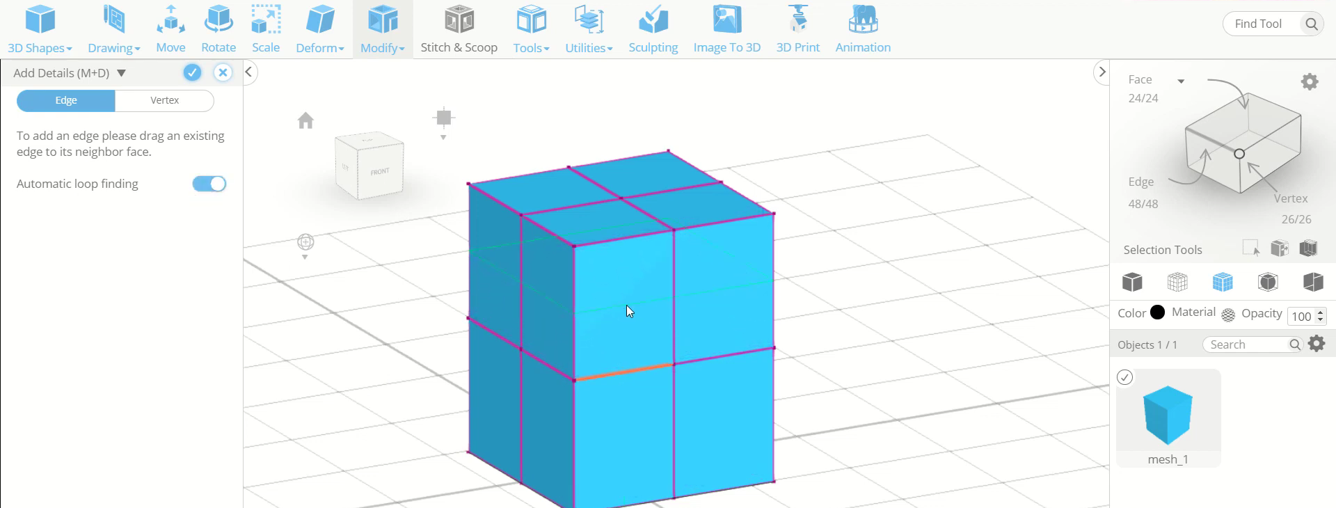
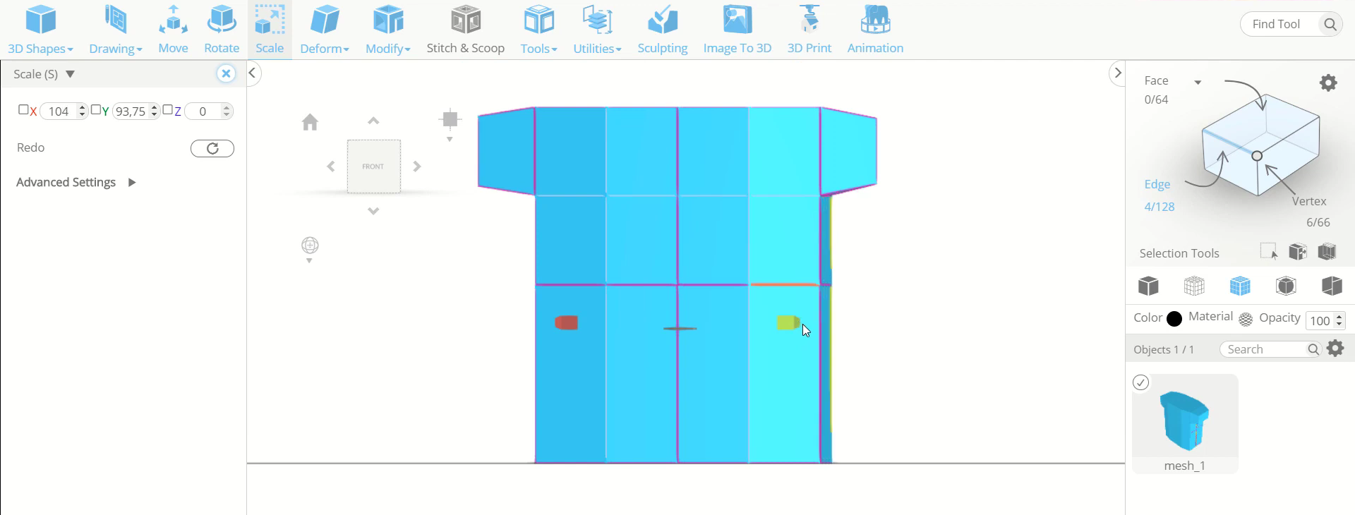
Step3: Add edges on the upper division
Now, go to modify and select the add details tool. Opt for edge and automatic loop finding. Then add an horizontal edge on the upper part. After that, scale the cube along the blue axis towards the inside.
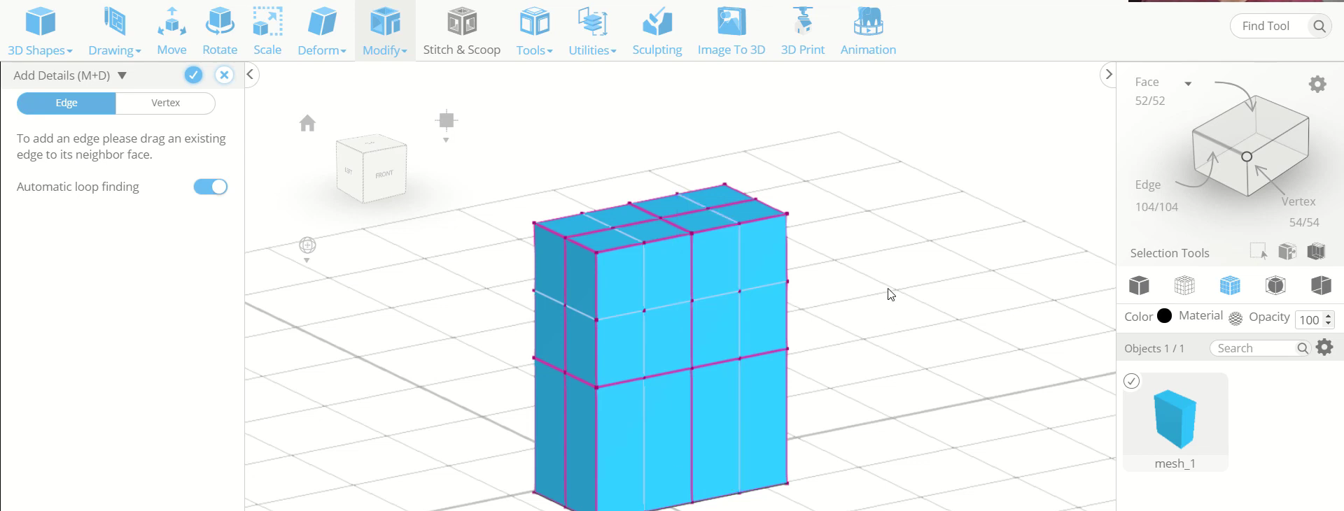
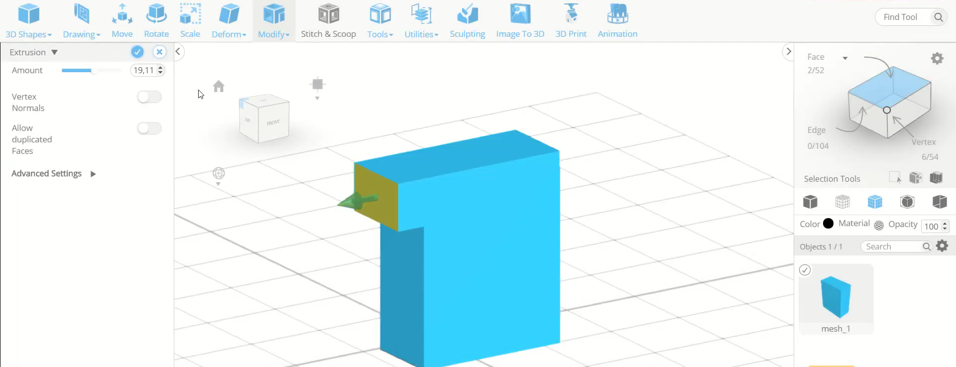
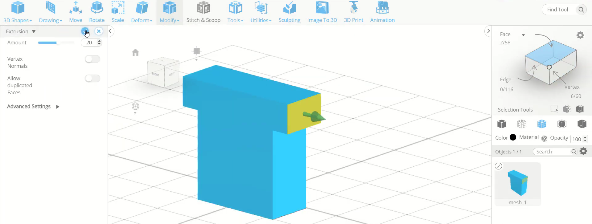
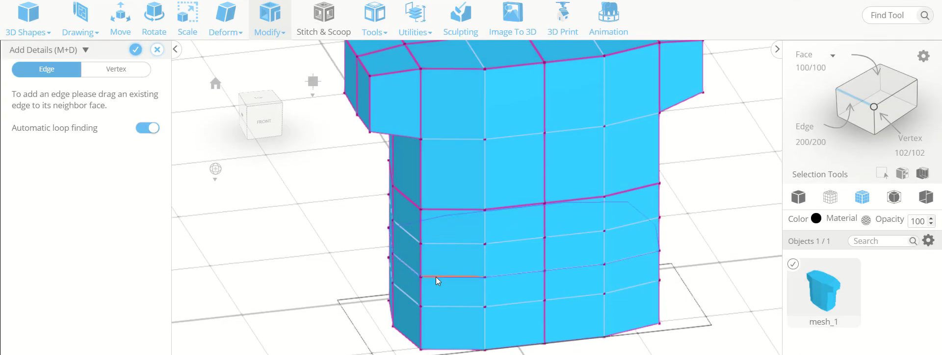
Step4: Add vertical edges and extrude the faces
Next, add two vertical edges on each part of the division. Then opt for face selection and select the top two faces from one of the sides. After that, go to tools and select the extrusion tool. Extrude these faces to an amount of 20. Repeat the same step on the opposite side.
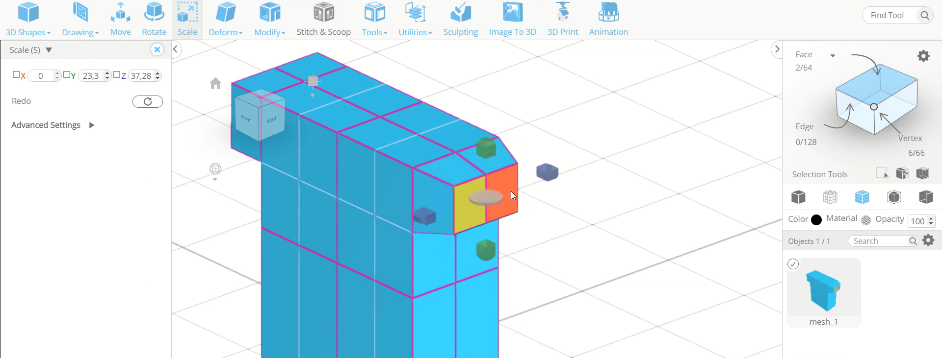
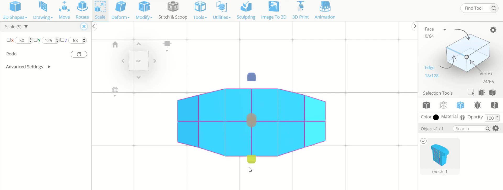
Step5: Scale the faces along different axes
Now, use the scale tool and scale these two pairs of faces to a smaller size, from the centre. Then opt for edge selection and select all the vertical edges from both back and front sides. After that change to the top view and scale them outwards along the blue axis.
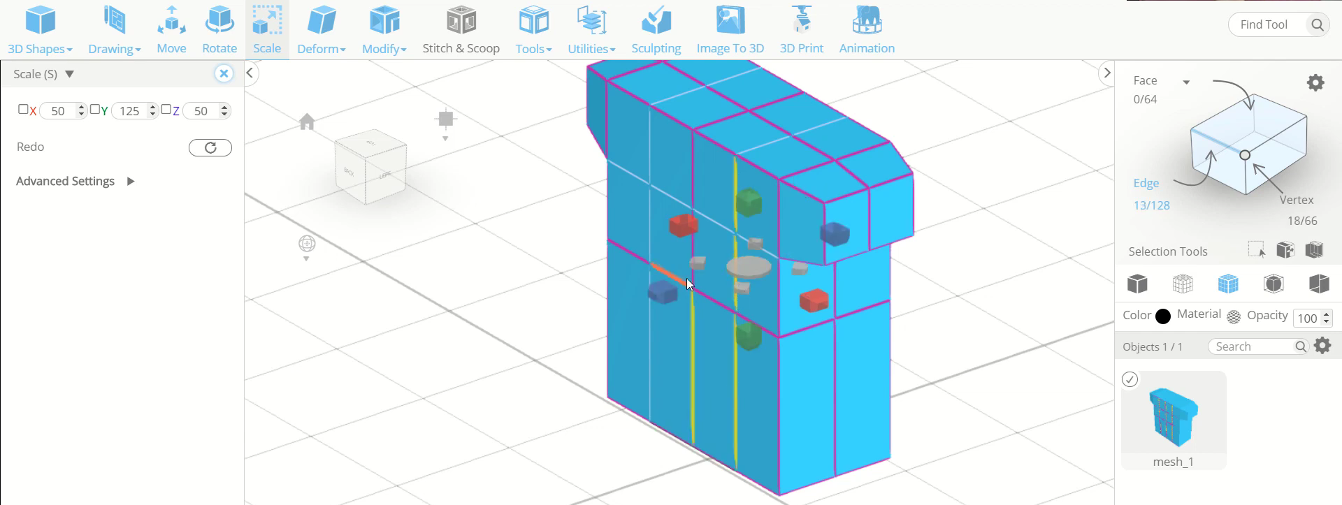
Step6: Repeat the same steps with the vertical edges of the other side
Next, repeat the same steps with the vertical edges of the 3/4th area of the sides. Then select the middle lower edges of the extrude faces and scale them towards downwards along the green axis.
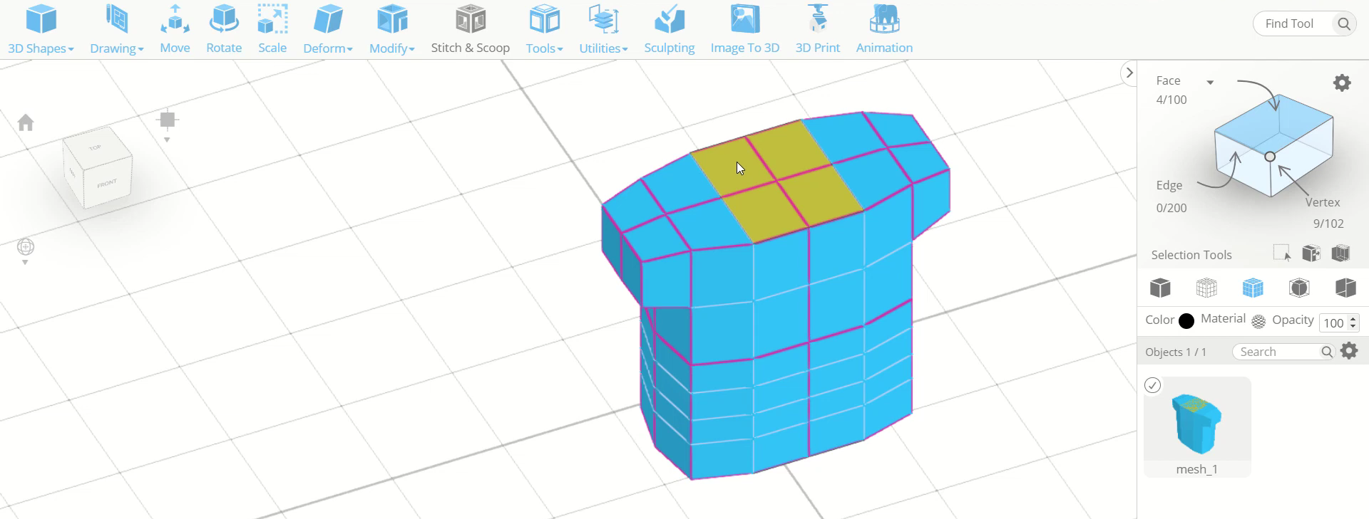
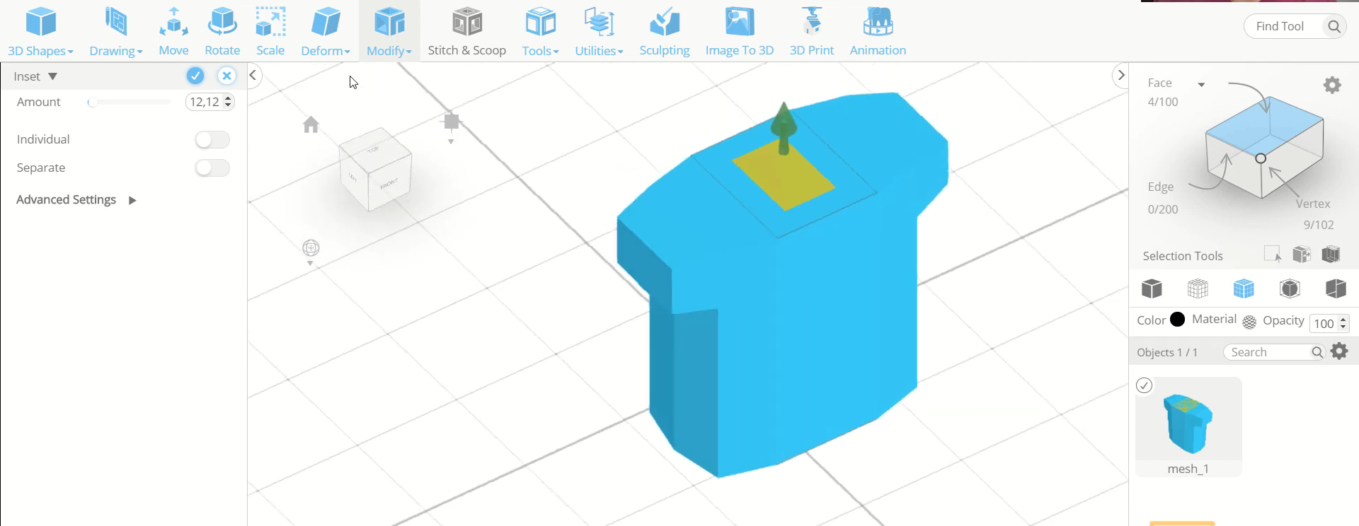
Step7: Add edges and inset the faces
Now, we will add three horizontal edges on the lower division of the front side. Then opt for face selection and select the middle four faces of the top side. After that, go to modify and select the inset tool. Set it to an amount of 12.
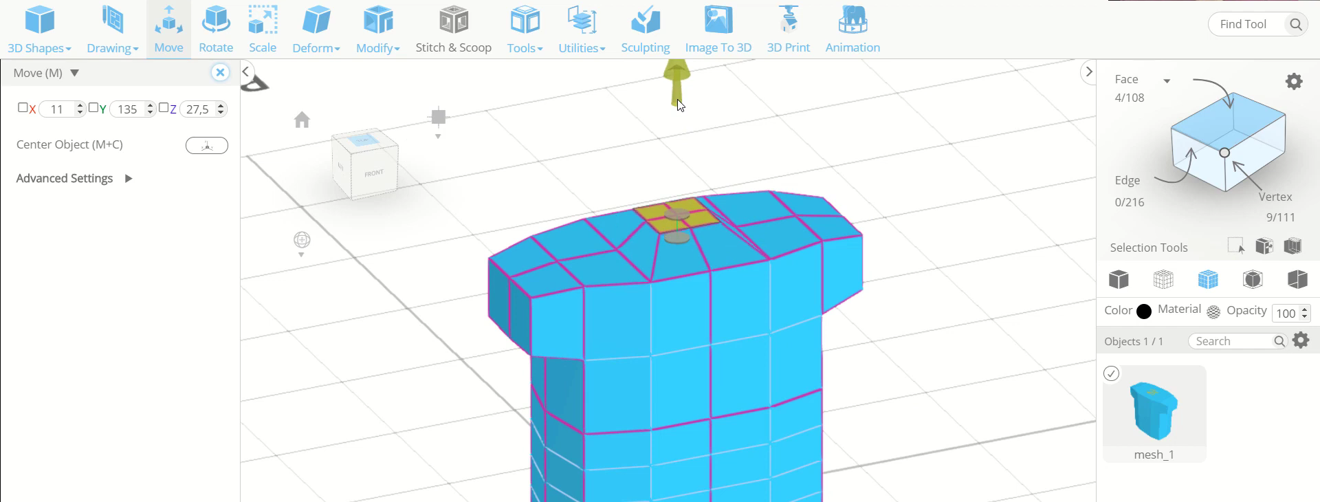
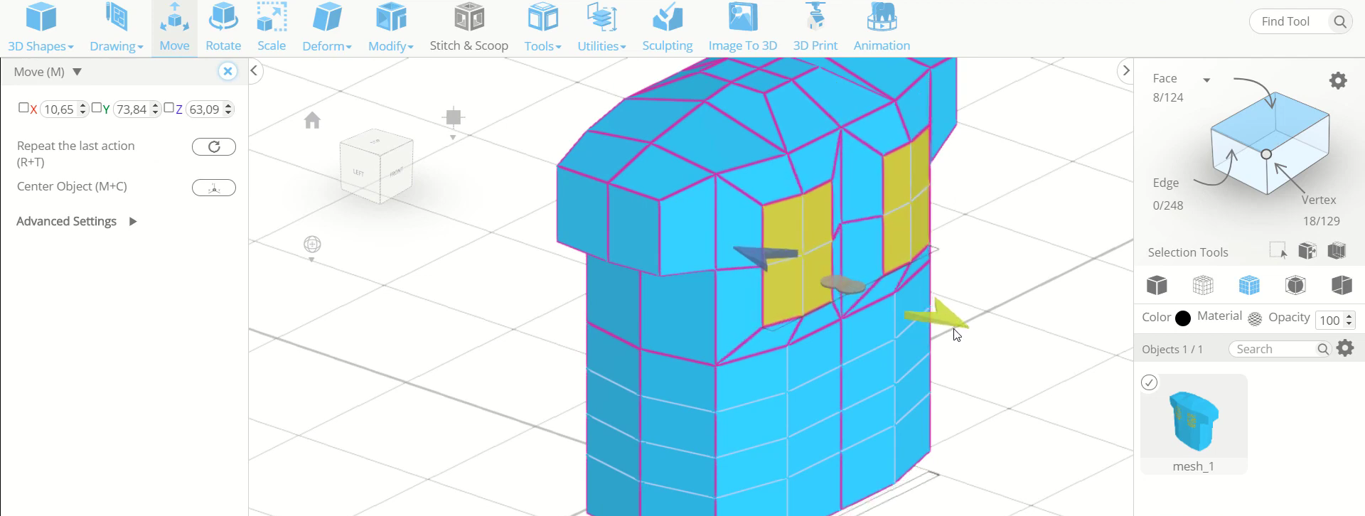
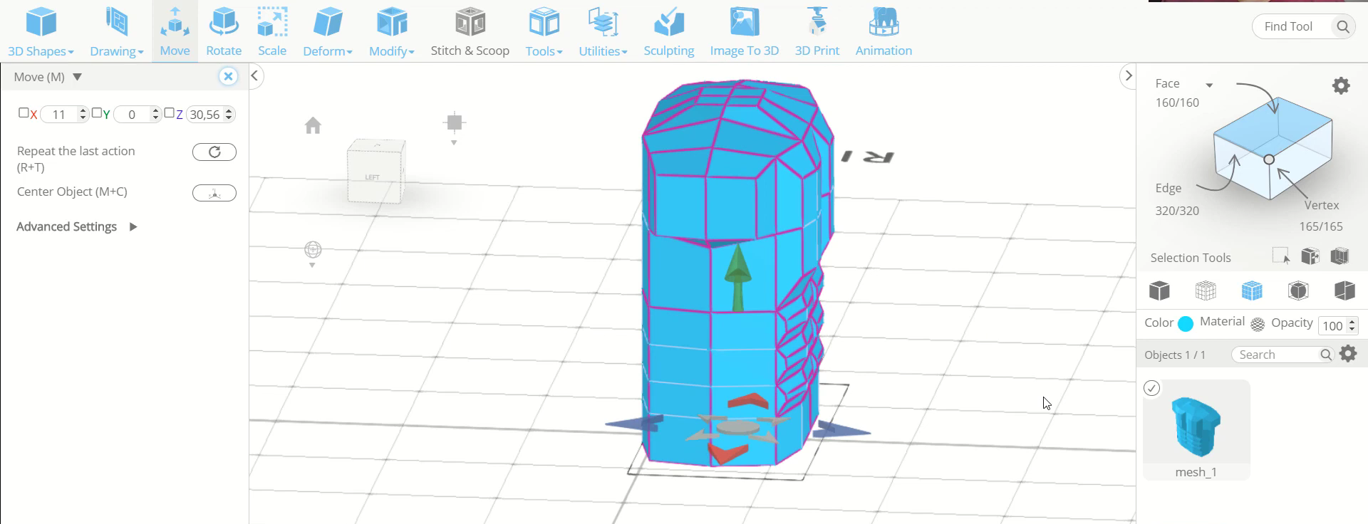
Step8: Scale the sides and move the faces towards the top
Next, use the scale tool and scale the sides of the selected faces along the blue axis towards the inside. Then use the move tool to move these selected faces to the top.
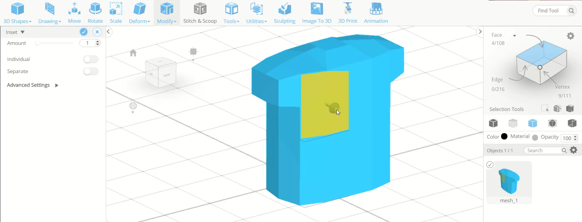
Step9: Inset the faces of the chest part
Now, opt for face selection and select the four faces of the left chest part. Then inset it to an amount of 12. Repeat the same step with the other side.
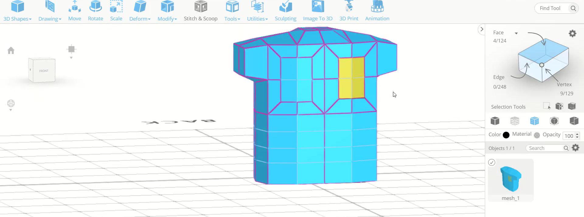
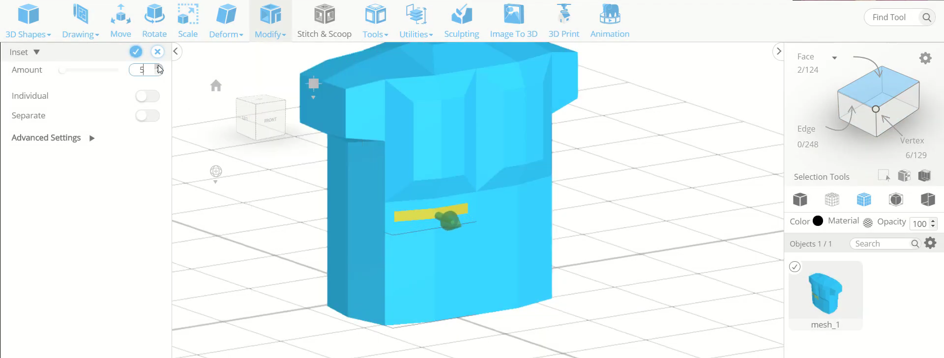
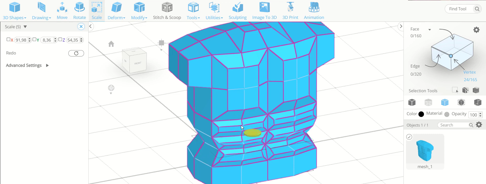
Step10: Inset the consecutive faces of the lower division
Next, select all the modified faces and move the outwards along the blue axis. Then select the consecutive two faces of the upper part of the lower division. After that, inset it to an amount of 5. Repeat the same step with all the consecutives faces of both the sides.
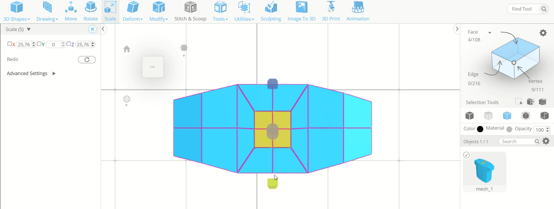
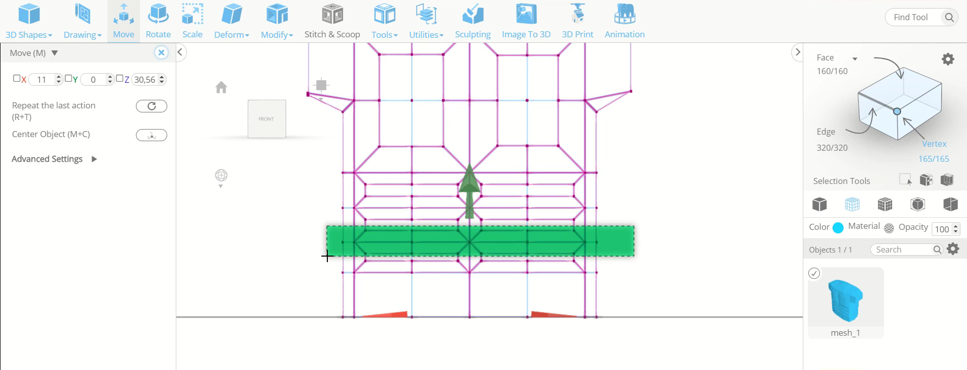
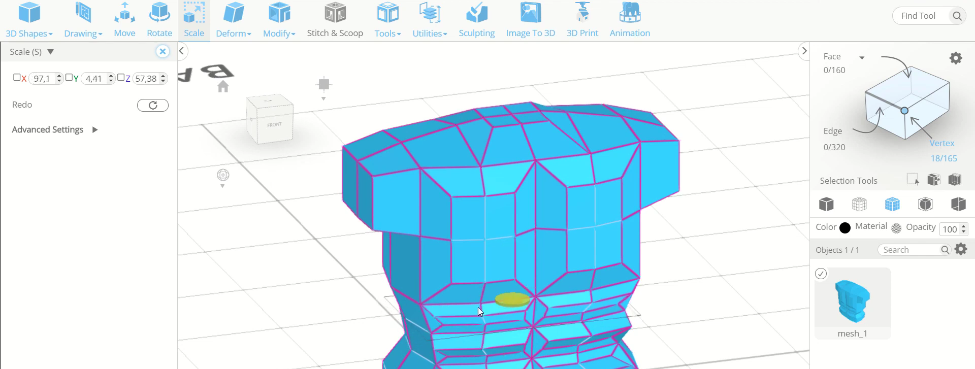
Step11: Scale the vertices towards inside
Now, select all the modified faces and move them outwards. Then change to wireframe view and opt for vertex selection. After that, select all the vertices as shown in the image. Then scale it towards the inside from the centre.
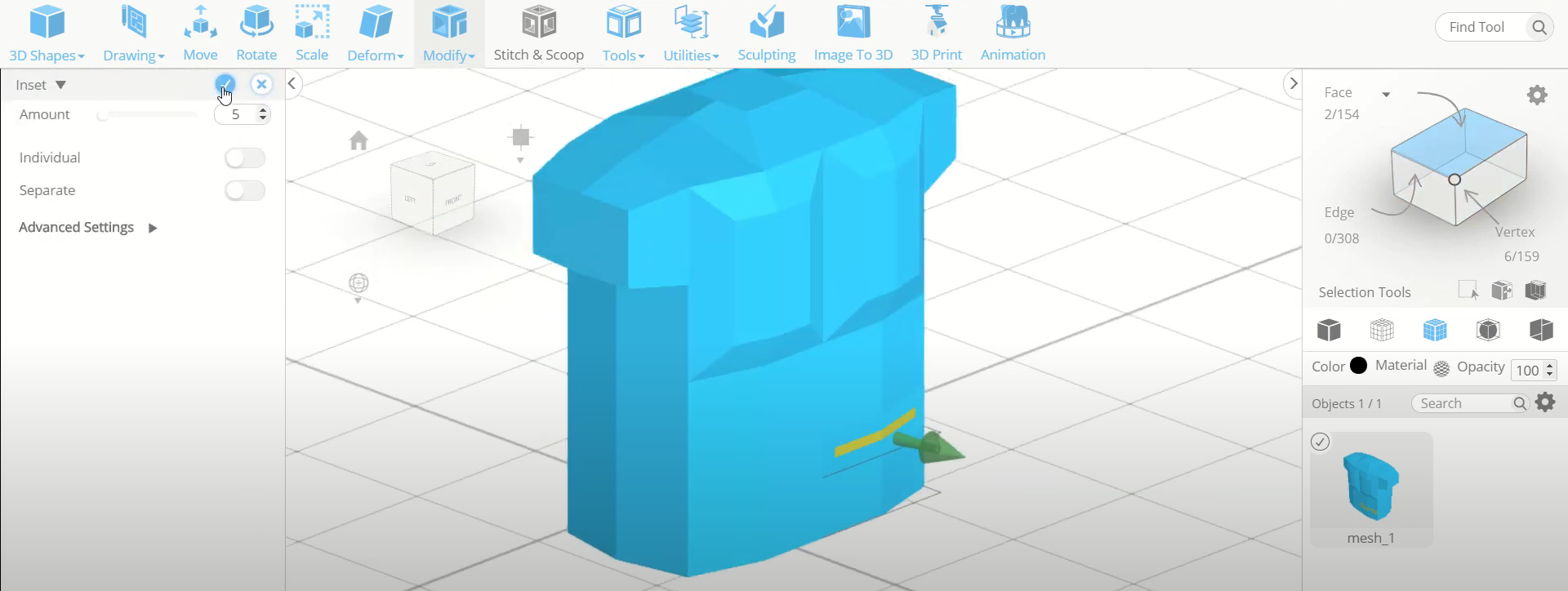
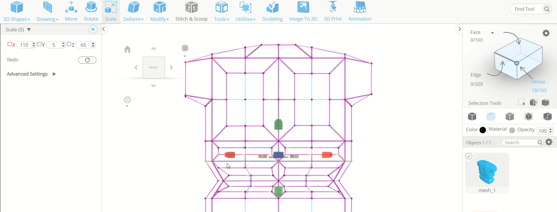
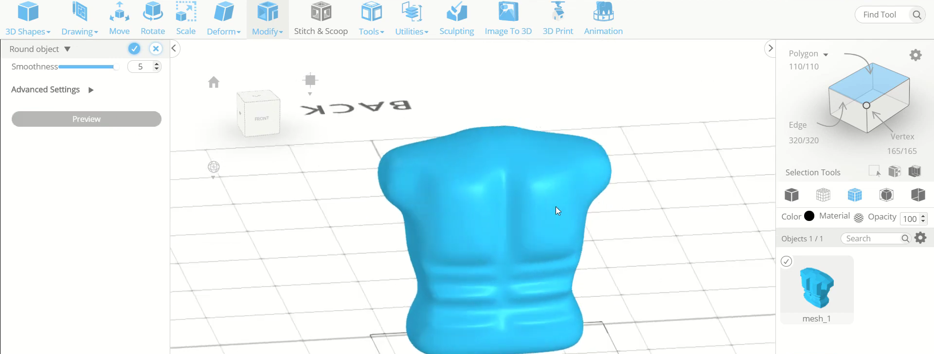
Step12: Add smoothness to the object
Next, repeat the same step with the upper set of vertices. Then go to modify and select round objects tool. Set the smoothness to 5.
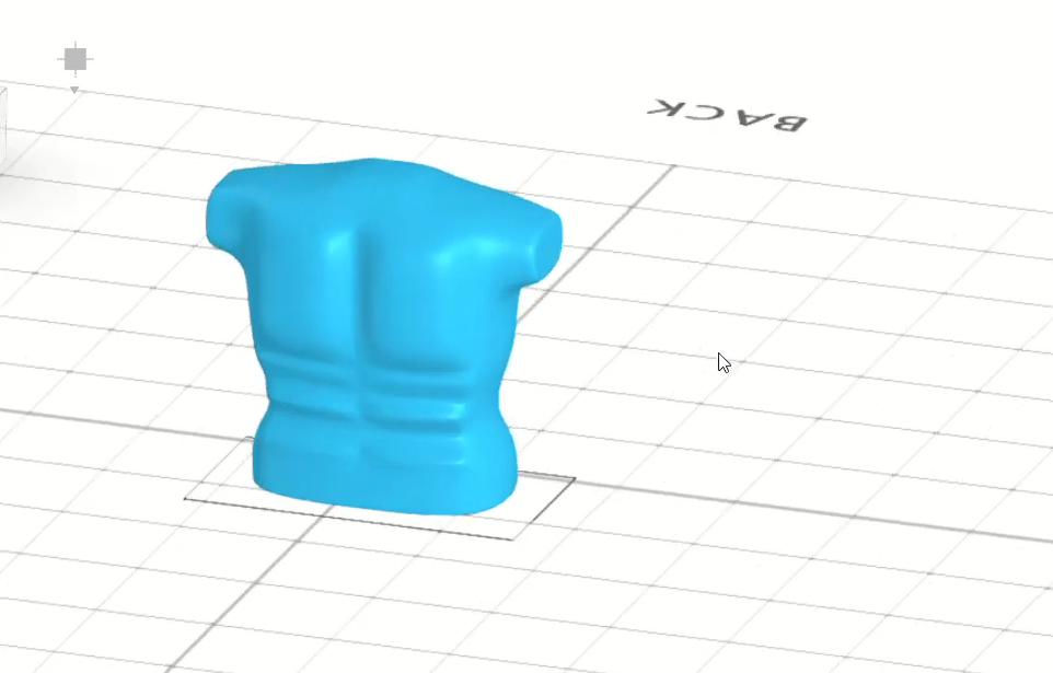
Conclusion: Therefore, we created a 3D upper body in SelfCAD
We have 3D designed the upper piece of the body utilizing various options and tools of SelfCAD. You can utilize a basically indistinguishable method to 3D design other 3D models of your decision.