In this tutorial article, we will be designing 3D hinges in SelfCAD.
3D designing is becoming famous in many fields. Previously, it was just an expertise being mastered by experts in structural designing, mechanical designing, and different callings. Be that as it may, with the appearance of simple to-utilise programs like SelfCAD, everybody, no matter what their experience, can get everything rolling with the product without sweat. What makes SelfCAD exceptional is that as well as being not difficult to utilise, it's likewise sufficiently strong to be utilised to make complex designs. Its connection point is outstandingly regular, and uncommonly expected for students. It has a wide variety of instruments, including express devices expected to manage the model for genuine 3D printing.
In this article, we will design 3D hinges in SelfCAD. We will completely go through the cycles and clarification of every single step.
You can also visit our page for more such articles like how to design a 3D screwdriver, etc.
So, let's begin!
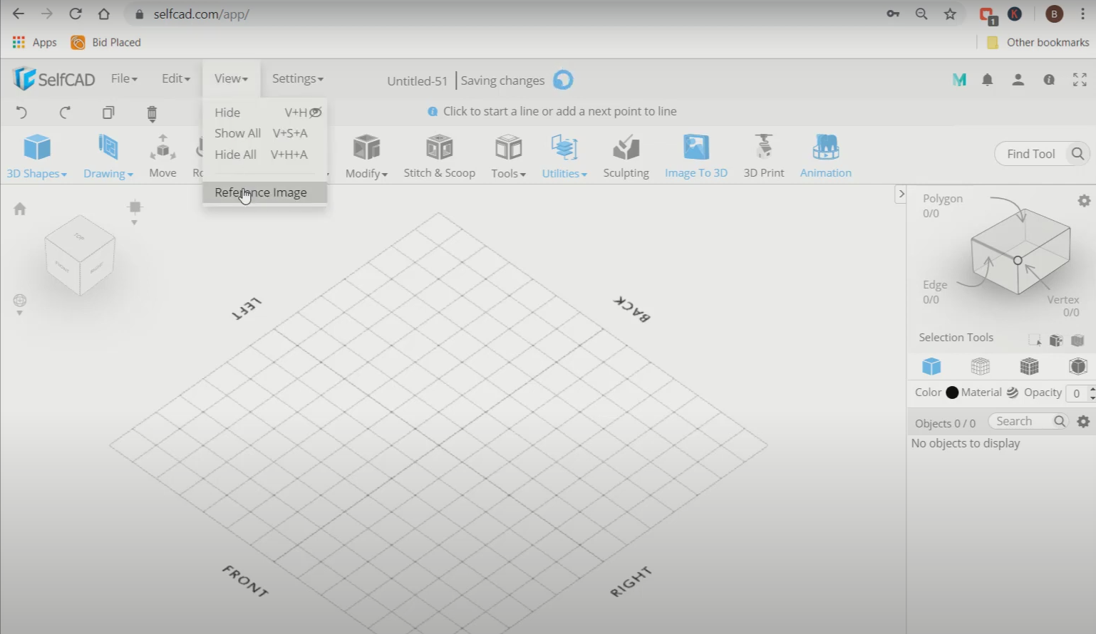
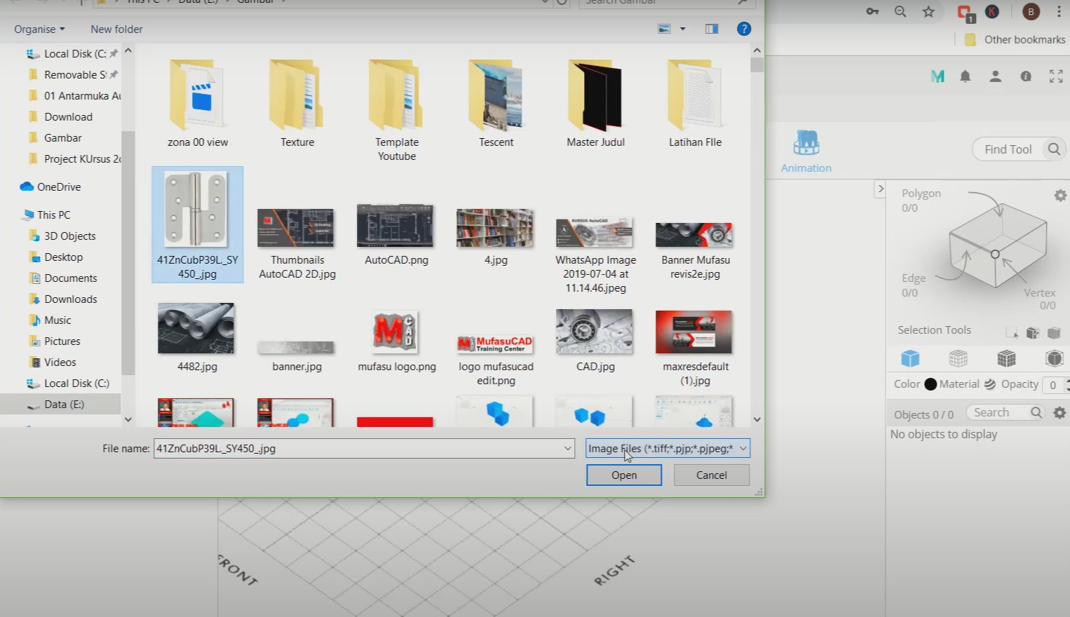
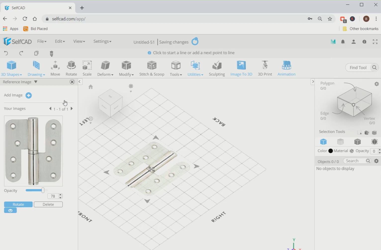
Step1: Add a reference image
First of all, we will go to views and select the reference image. Then add an image of a hinge. Reduce its opacity to 78.
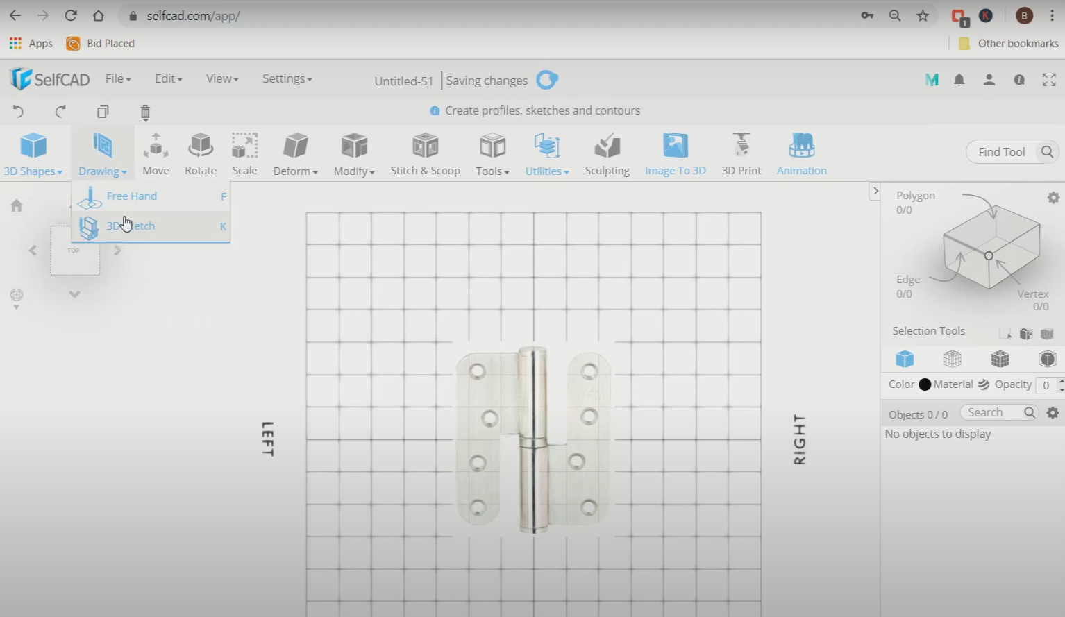
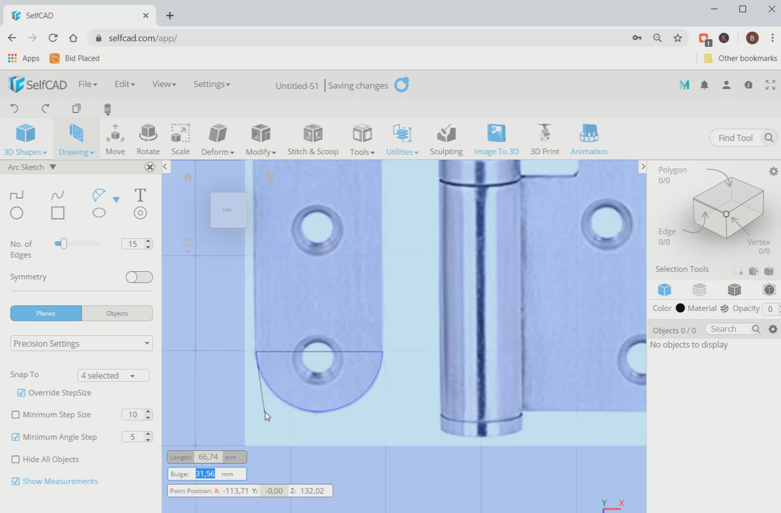
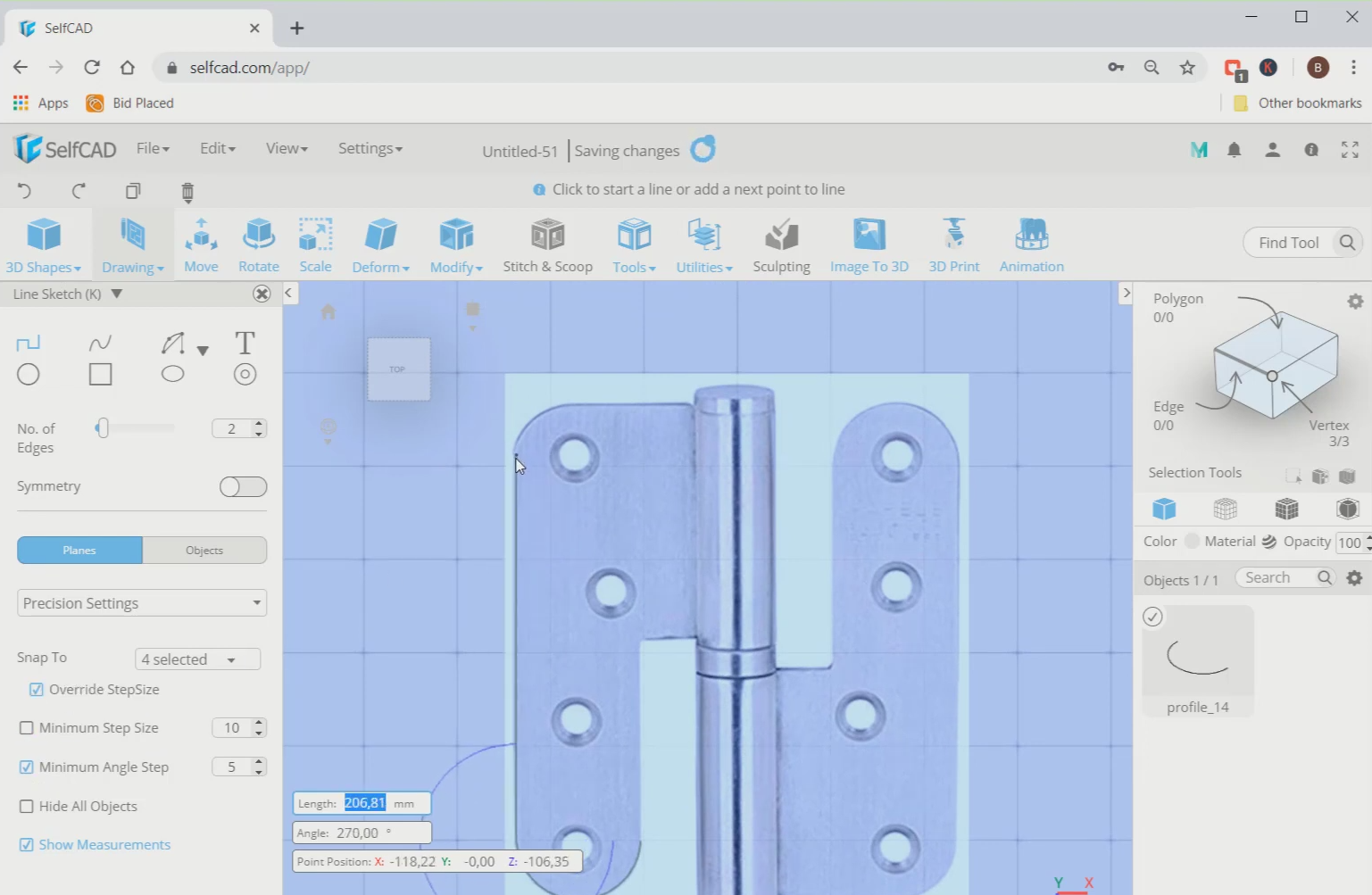
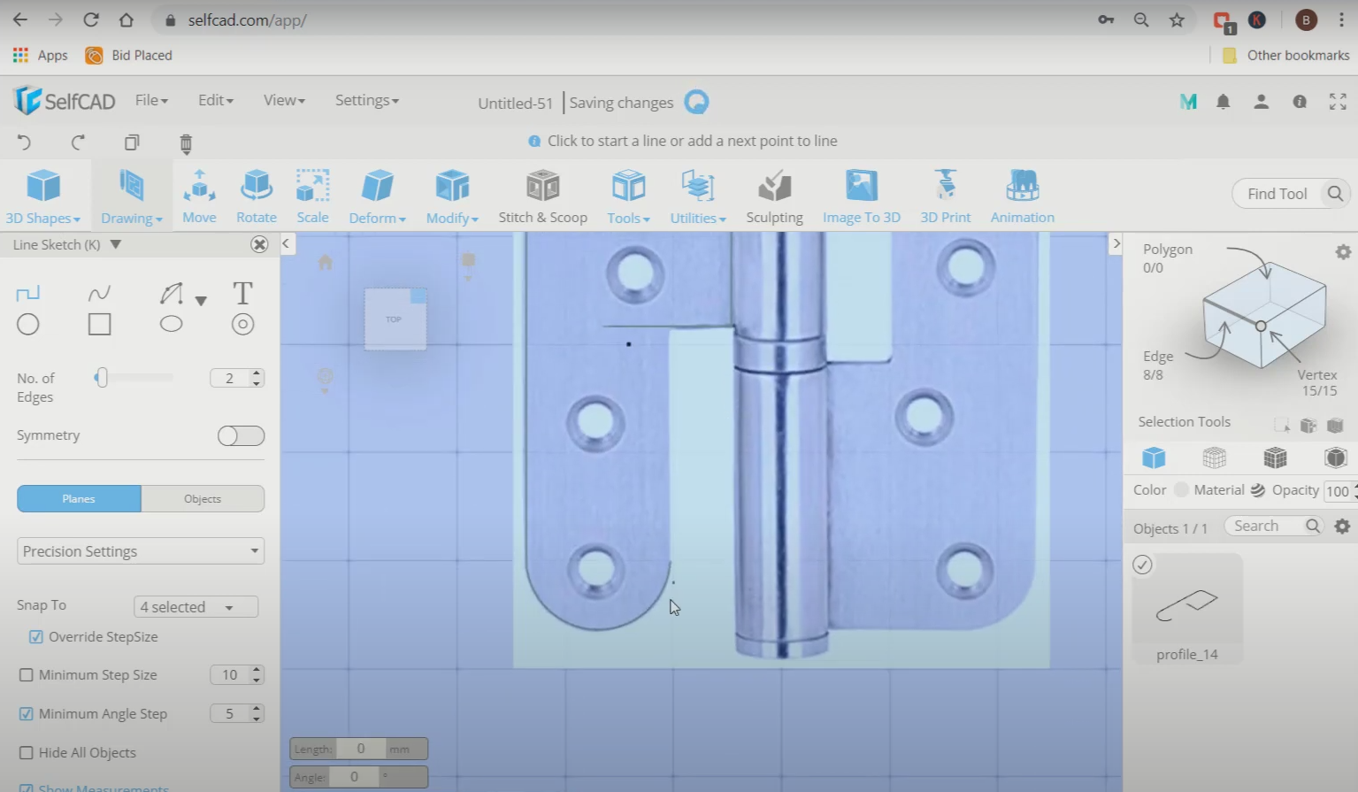
Step2: Trace the left side of the reference image
Next, set the top view and select the 3D sketch. Then select the 2-point arc tool, activate the minimum angle step option and trace the curved lines with this. We will use line sketch to trace the straight lines. With the help of these two sketches, trace the left side of the image, as shown in the image below.
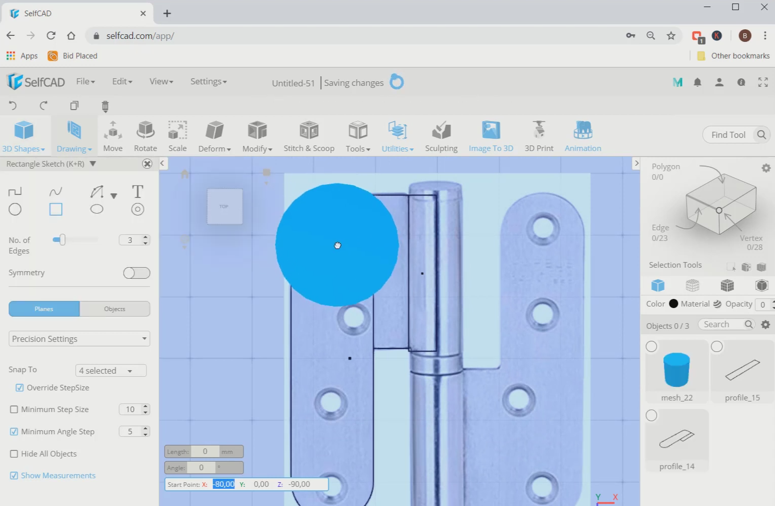
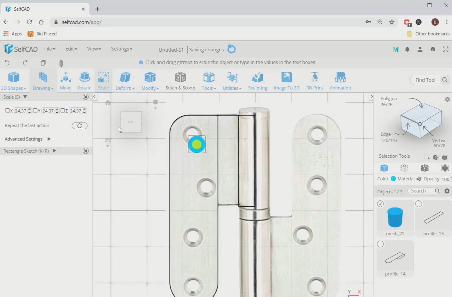
Step3: Trace the middle part and add a cylinder
Now, select the rectangle sketch and trace the quarter part of the middle image. Then go to the 3D shapes and insert a cylinder in the working interface. After that, use the scale tool and scale it to a smaller size from the centre.
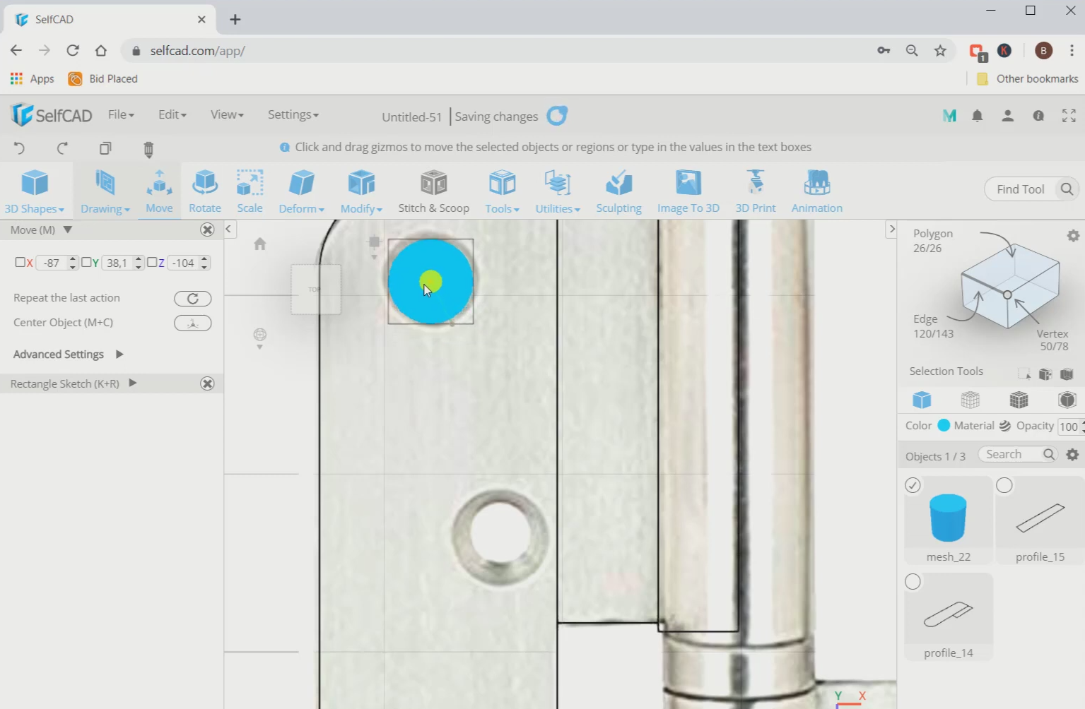
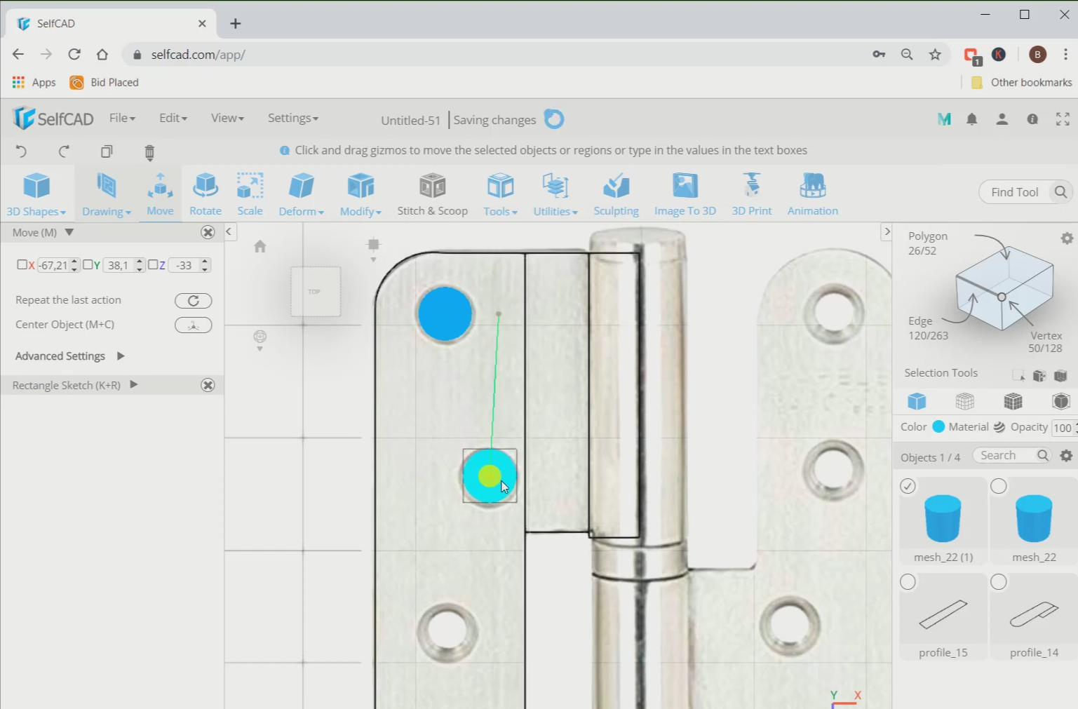
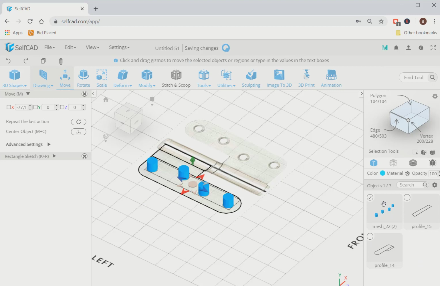
Step4: Use move tool to move the objects towards the circle
Next, use the move tool and move it to a circular part of the reference image. Then copy this using the copy option and move it to another circle. Repeat this step until all the circles are filled on the left side.
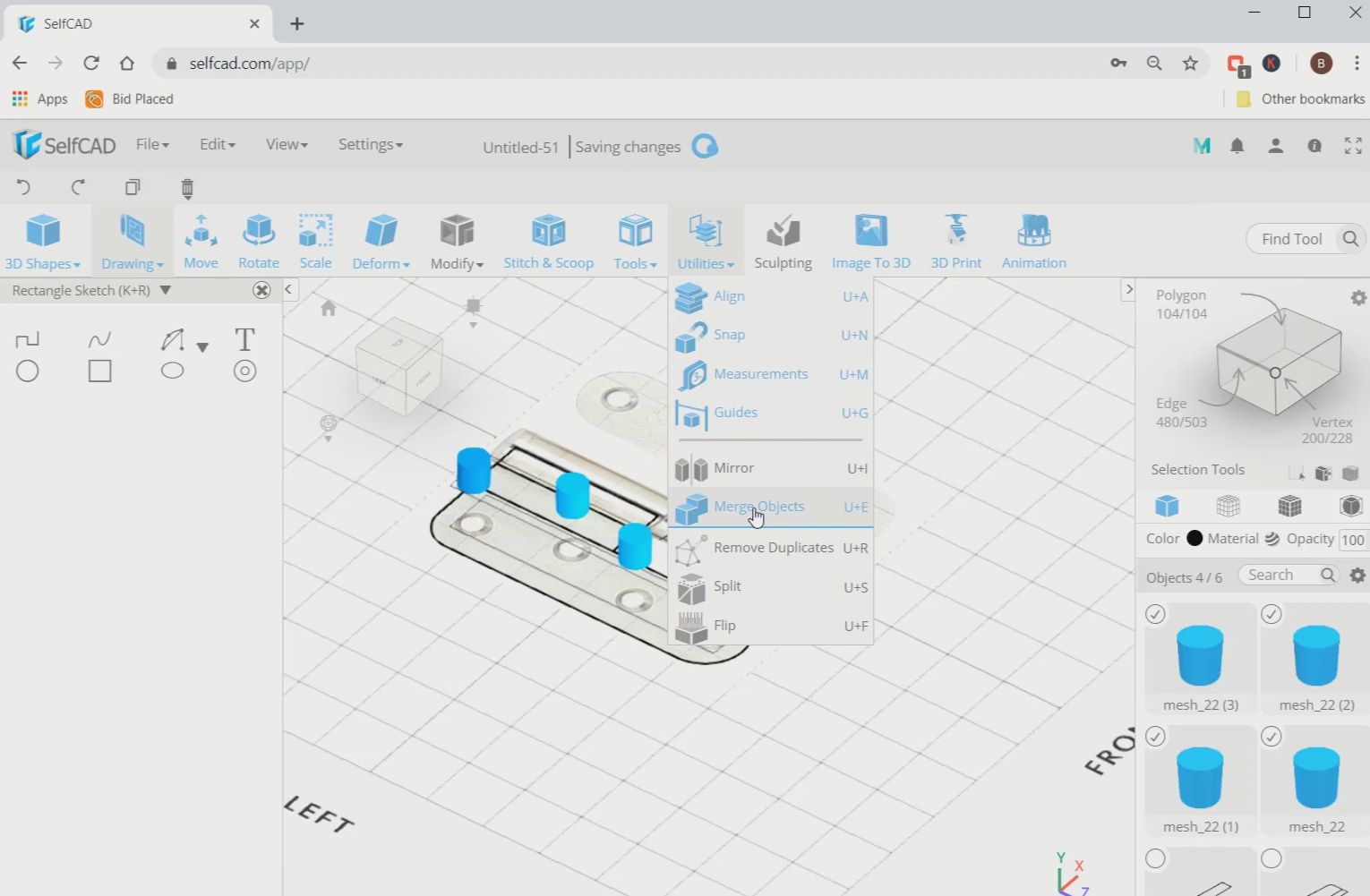
Step5: Merge the cylinders
Now, select all the cylinders, go to utilities and select the merge object option. Then move these cylinders along the green axis to the bottom.
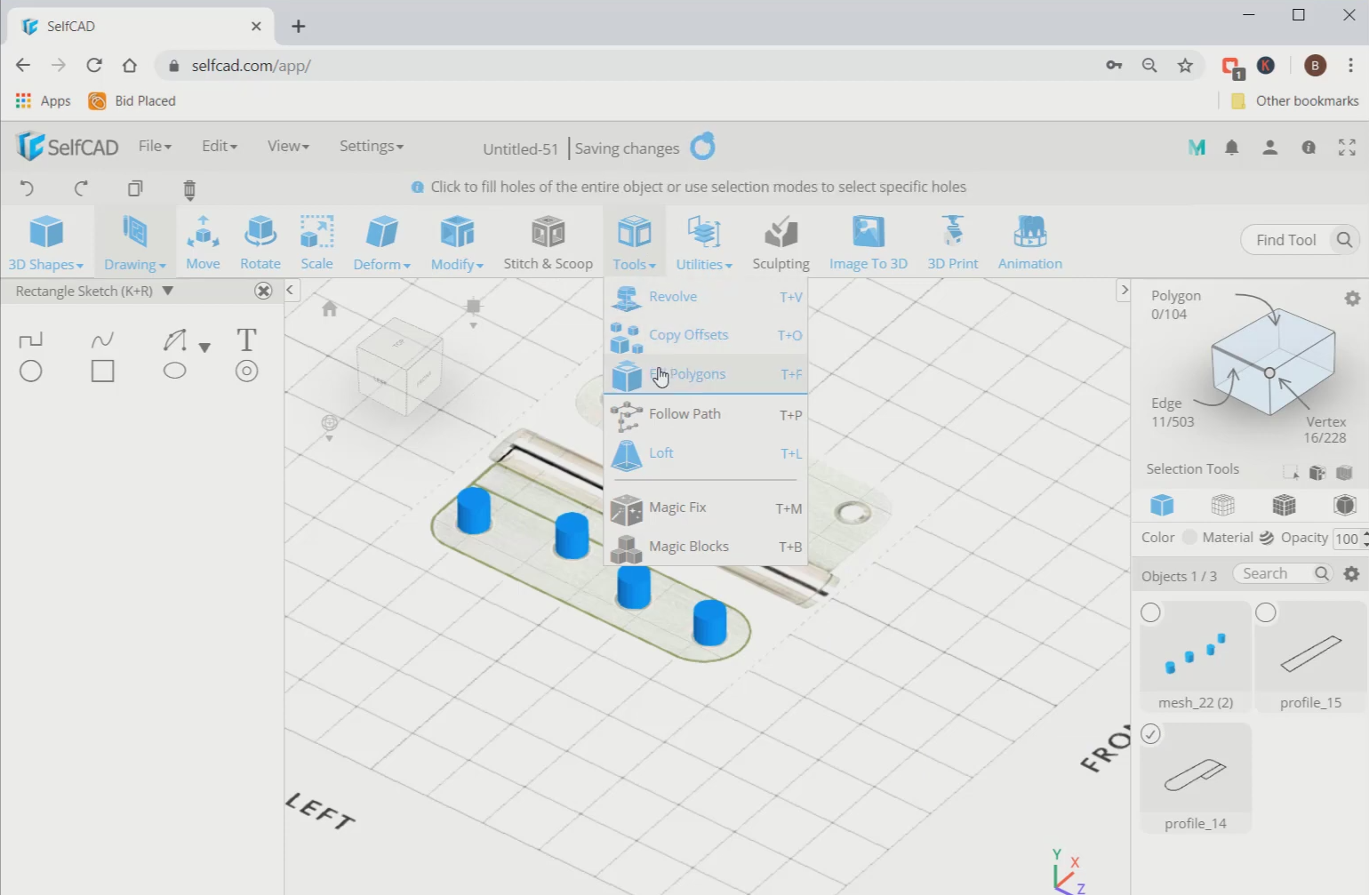
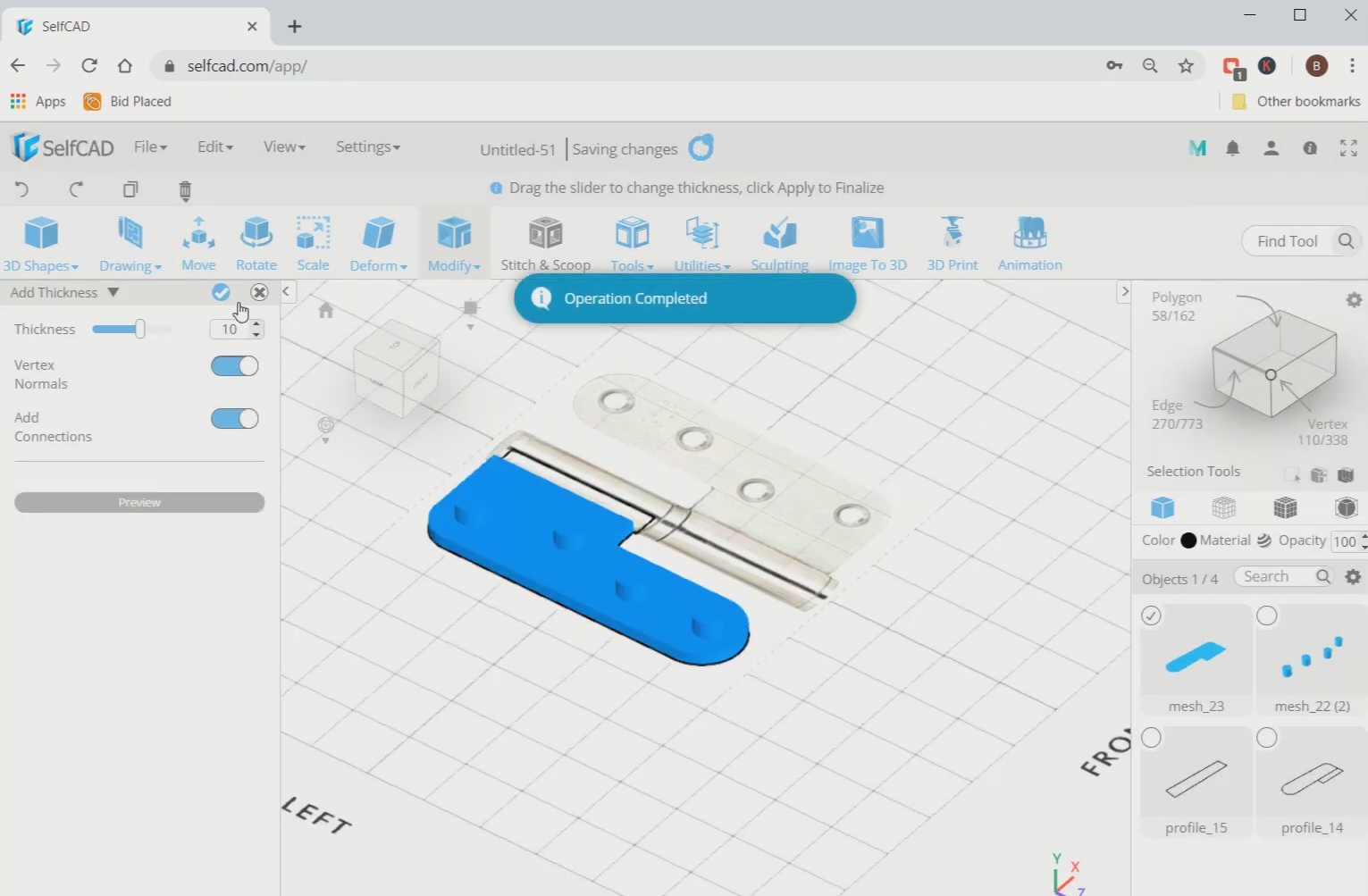
Step6: Fill the polygons and add thickness
Next, select the left traced sketch, go to tools and select fill polygon option. Then go to modify and select the add thickness tool. Set the thickness to 10.
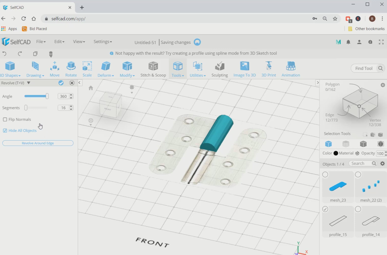
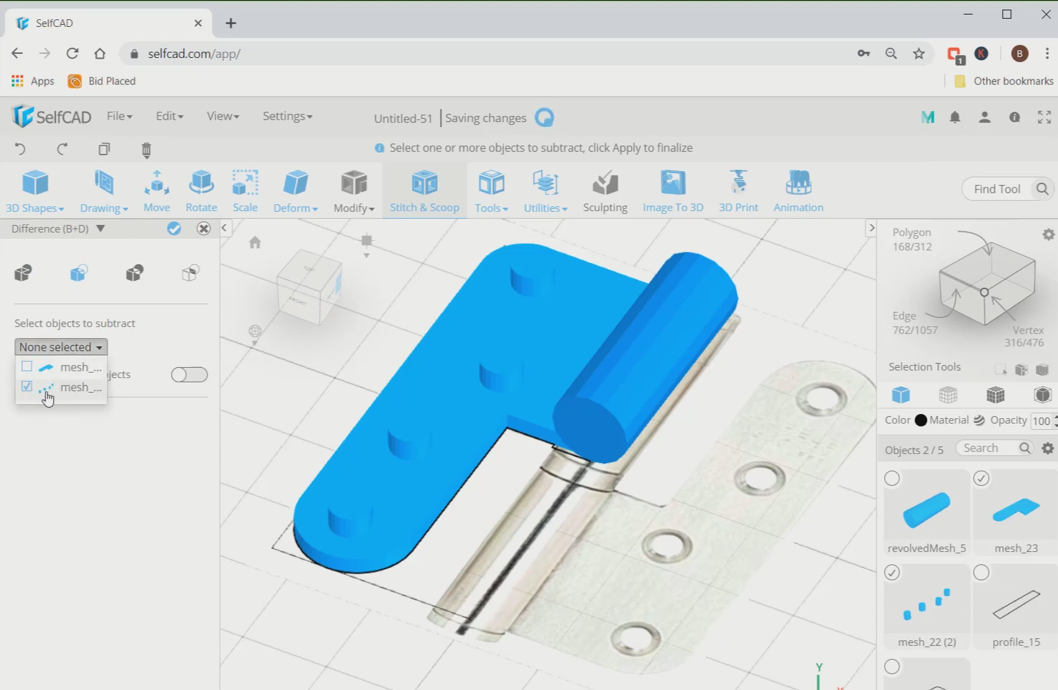
Step7: Revolve the central objects and subtract the cylinders from the left profile
Now, select the middle sketch, go to tools and select the revolve option. Select revolve around the edge and select the middle edge as the reference edge. Then select the left sketch and the cylinders, go to stitch and scoop and select the difference option. Subtract it from the mesh22.
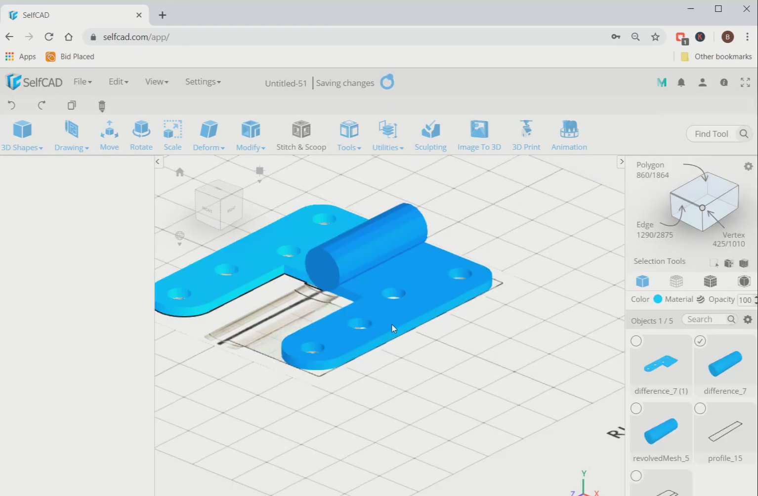
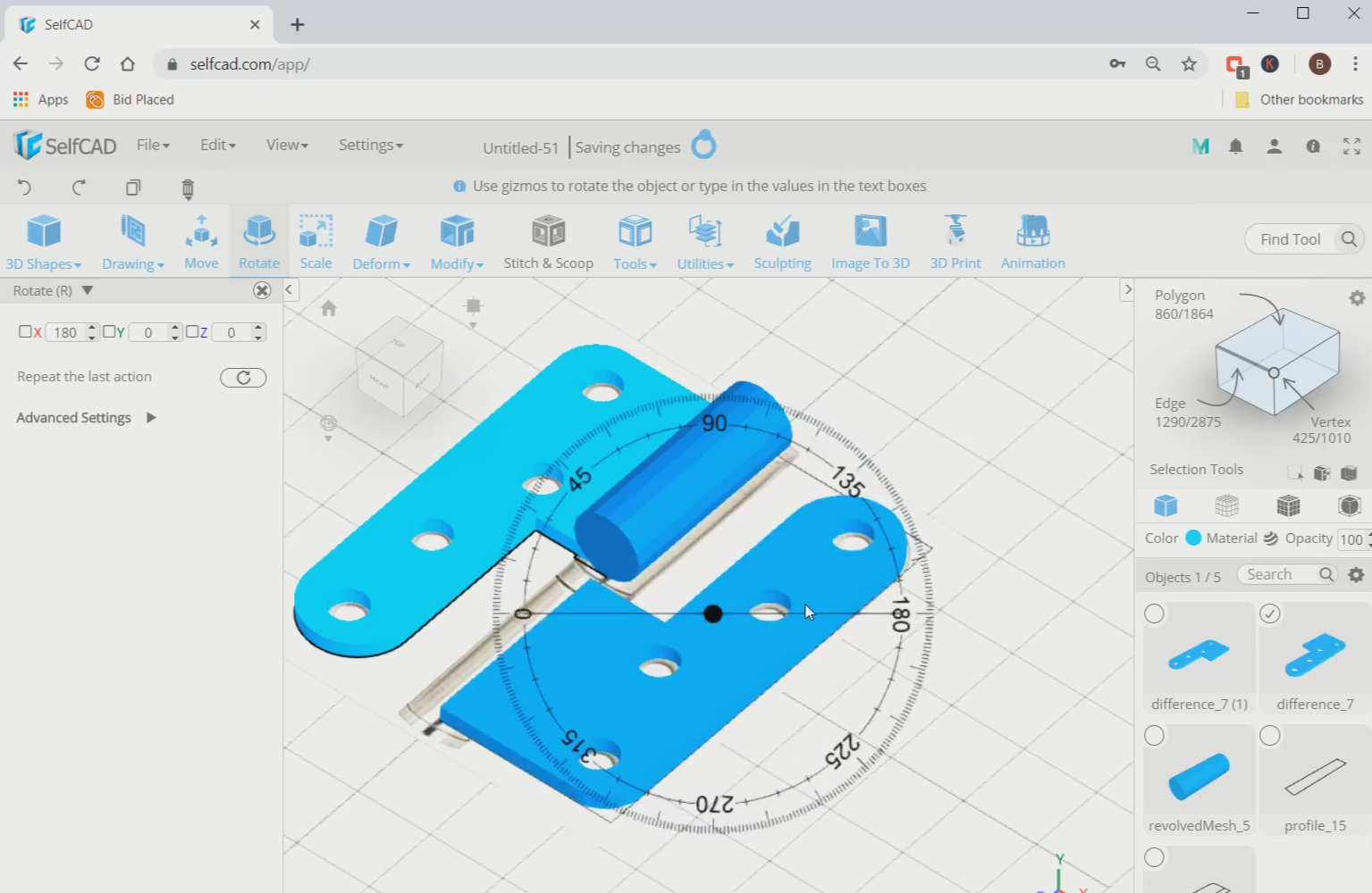
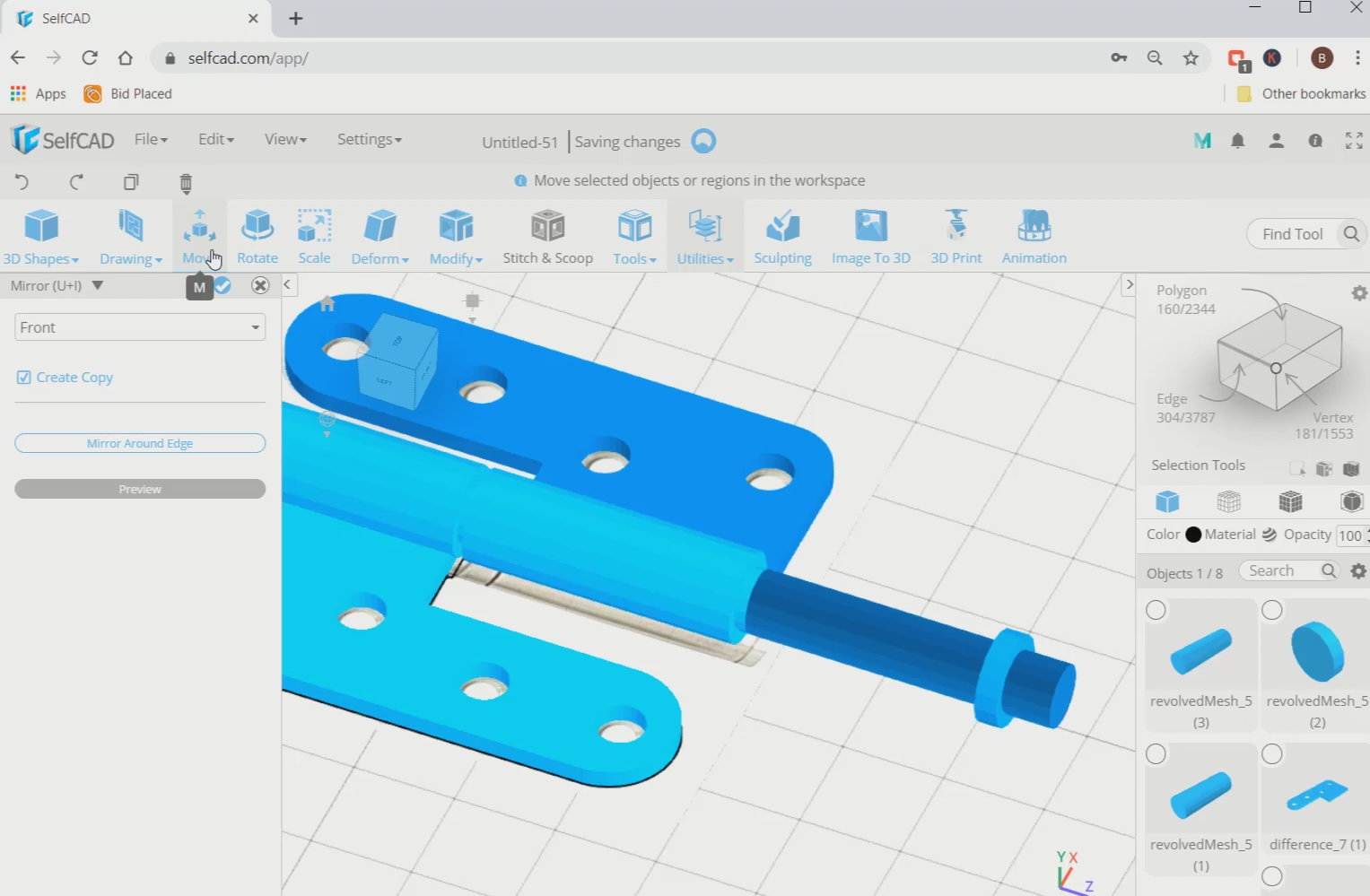
Step8: Mirror the objects and rotate them
Next, select the left object, go to utilities and select the mirror option. Set it to the right. Then rotate it using the rotate tool along the red axis in about 180 degrees.
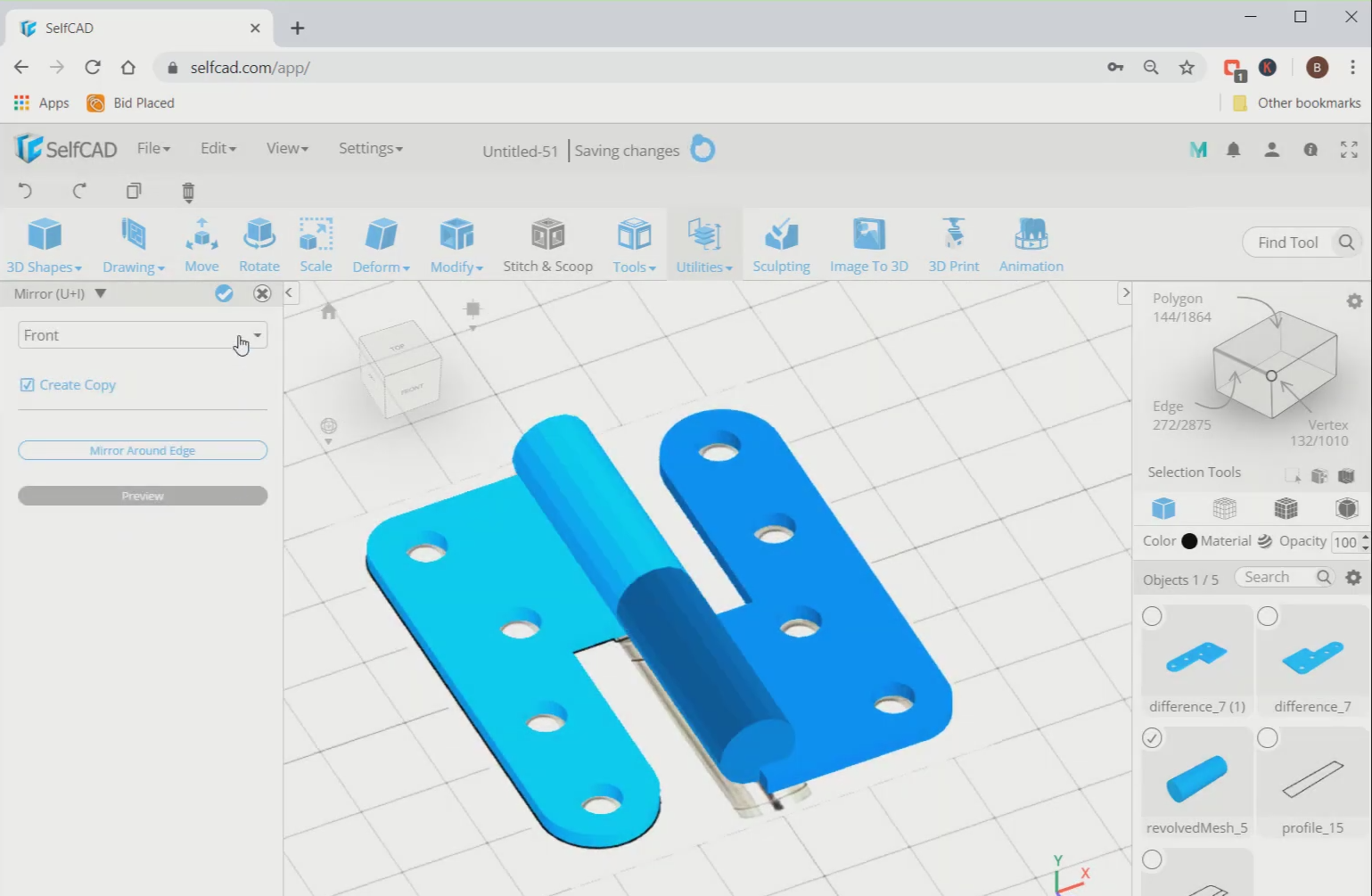
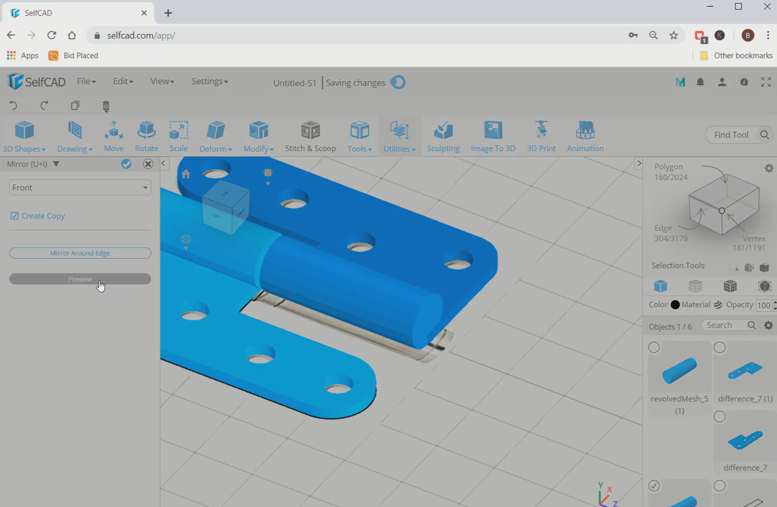
Step9: Mirror the middle object
Now, we will mirror the middle cylinder from the front. Then move the mirrored image towards the back.
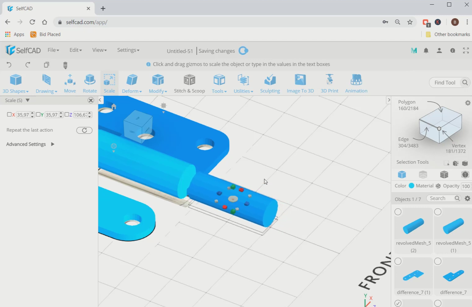
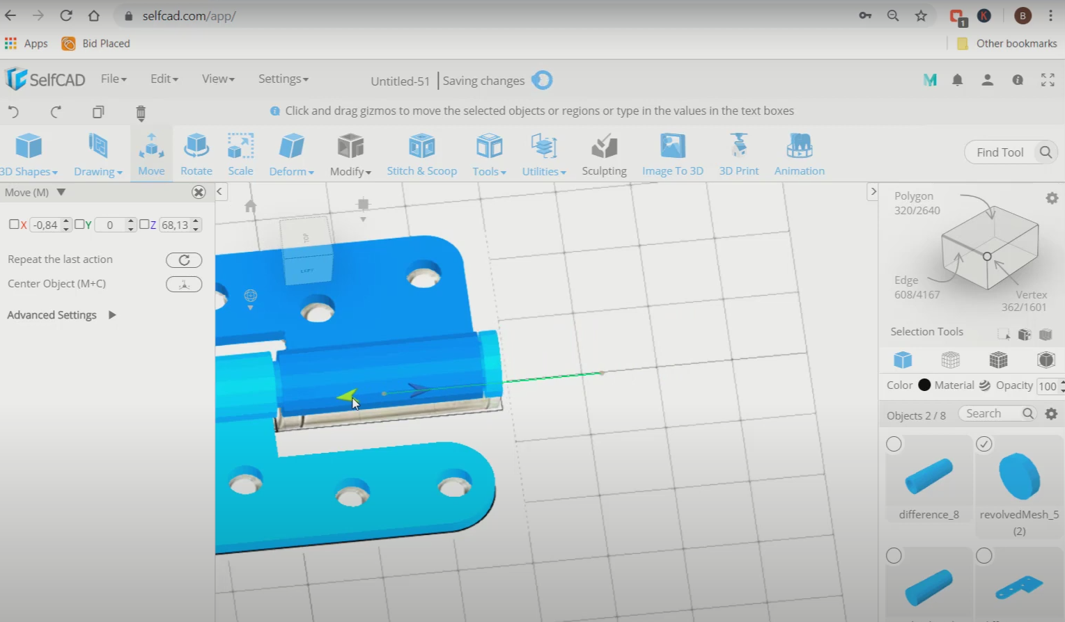
Step10: Scale the mirrored cylinder to a smaller size and move it towards the centre
Next, mirror that cylinder again. Then scale it to a smaller size. After that, insert it inside the lower cylinder using the move tool.
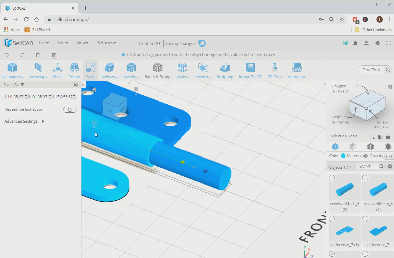
Step11: Mirror the internal cylinder
Now, again mirror that object and scale it to make a flattened figure. Then mirror the internal cylinder.
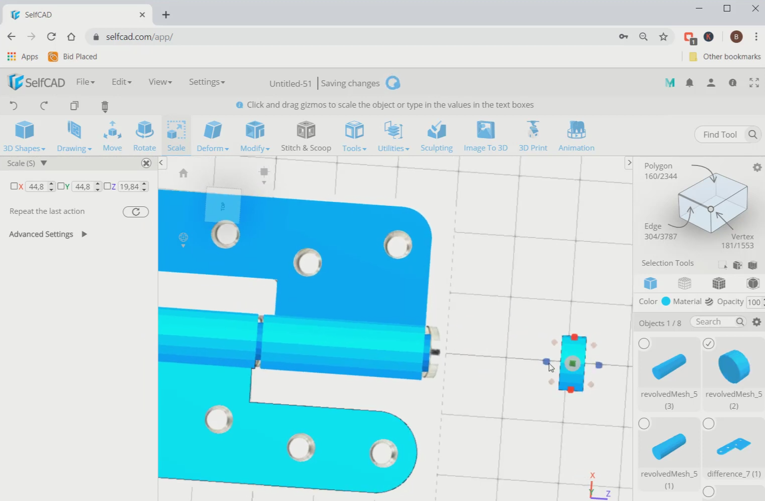
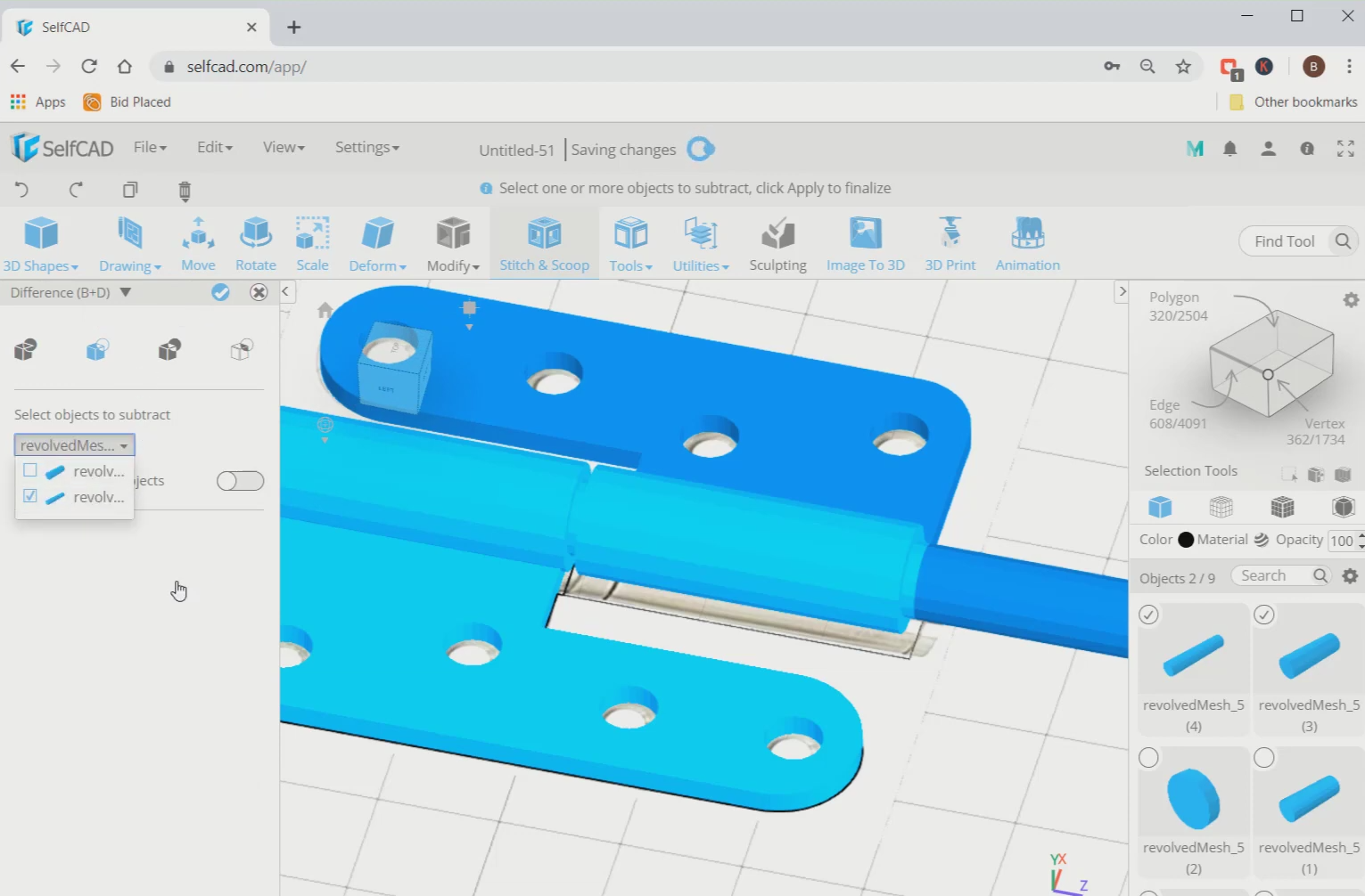
Step12: Subtract the smaller cylinder from the bigger one
Next, select the middle cylinder and the smaller cylinder inside it, go to stitch and scoop and select the difference option. Then subtract the smaller cylinder from the bigger one. After that, move the lower part towards the middle.
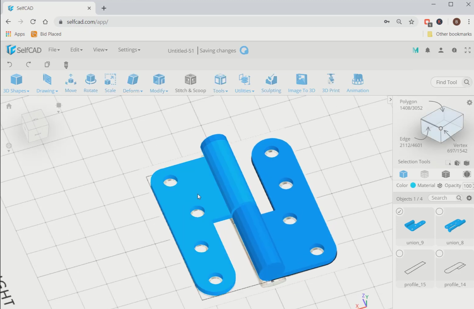
Conclusion: Hence, we created 3D hinges in SelfCAD
The means are smooth and can be effectively executed. As we probably are aware, SelfCAD simplifies the cycle, so it will be intriguing to design more 3D designs like this. Moreover, it's a genuinely sensible internet based design with an impressive number of clients. SelfCAD is presently being used in schools, homes, and associations all over the world.