Take your DIY radio to the next level by giving it Google Home Assistant capabilities!
The Google Home, in all its shapes and sizes, has a bunch of different ways to play music. There is Google Play Music, Spotify, Pandora, YouTube Music, or just regular old Bluetooth from your phone. However, one media option the Google Home lacks is an FM radio, a technology that was in use over 80 years before the release of the first Google Home.
You may think that traditional radio usage is in decline, but you may be surprised to learn that FM radio is still the most widely used media format by far. About 93% of the population listens to broadcast radio at least once per month. Broadcast radio is a $20 billion industry, which is far, far larger than any of the streaming services you may use on your phone. Even the largest streaming app today, Spotify, has forecasted annual revenue for 2019 of $7.5 billion. So, despite its age and less flashy marketing image, FM radio is still one of the primary ways people enjoy music.
Anyway, today we will be building an FM radio base for the Google Home Mini, enabling you to play any radio station you’d like by simply asking Google Assistant.
This project builds on the previous introduction to the SparkFun FM Radio Basic Breakout board. In this project we will expand upon the simple Arduino UNO sketch used in that article by covering many more advanced concepts:
- We will add a Wi-Fi connection so that the system can communicate with the Google Assistant.
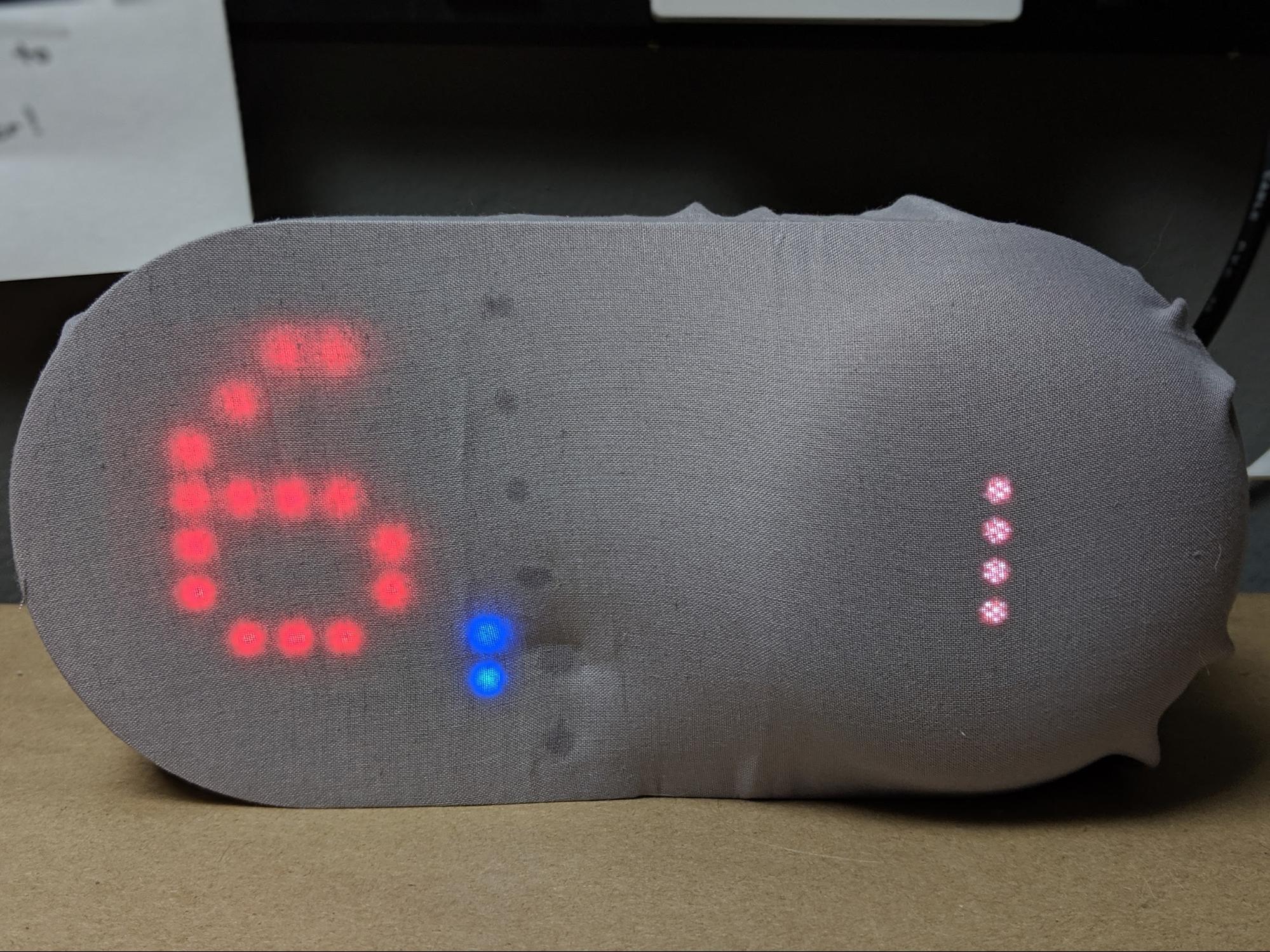
- The radio in this project has an LED matrix display that will provide useful information while in use.
- To house all the parts, and add to the aesthetics of the finished product, we will 3D print an enclosure.
- We will use IFTTT to allow the controller inside the radio to take commands from the Google Home Mini.
Let's get started.
Required Hardware
We will need a few parts to complete the build. The only part not listed in the table below is the 3D printed enclosure, which is discussed in more detail in its own section.
The last item you can choose to use or not use is some fabric that will eventually cover the Google Assistant radio. You can use any style of fabric you like.
3D Print the Enclosure
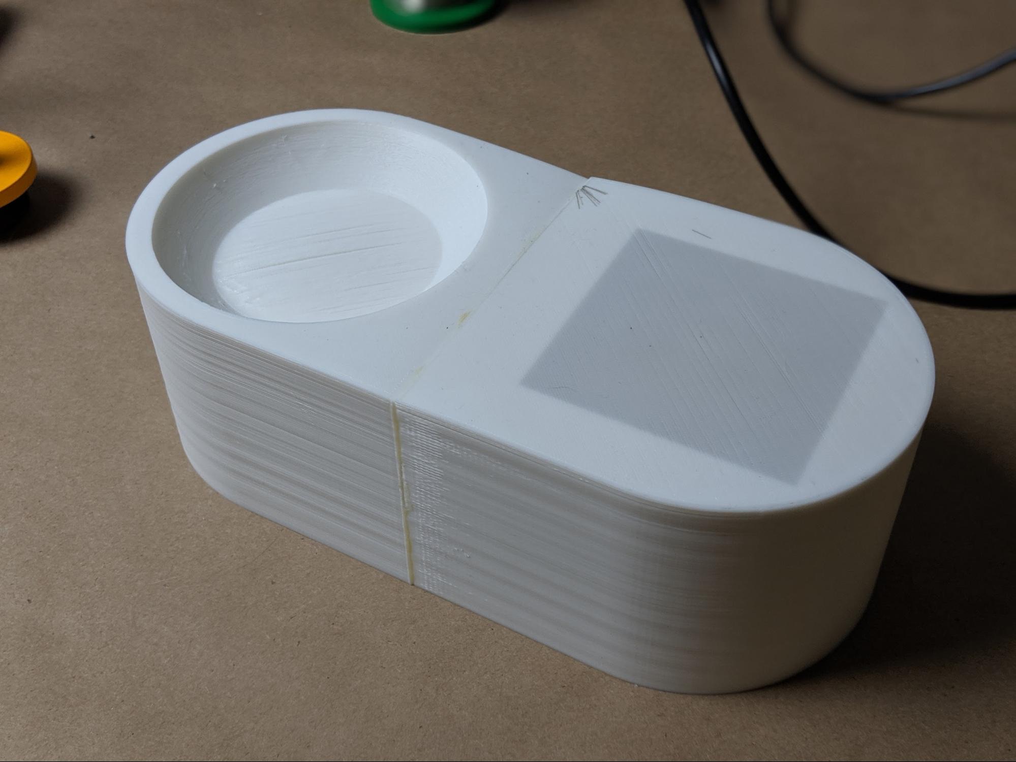
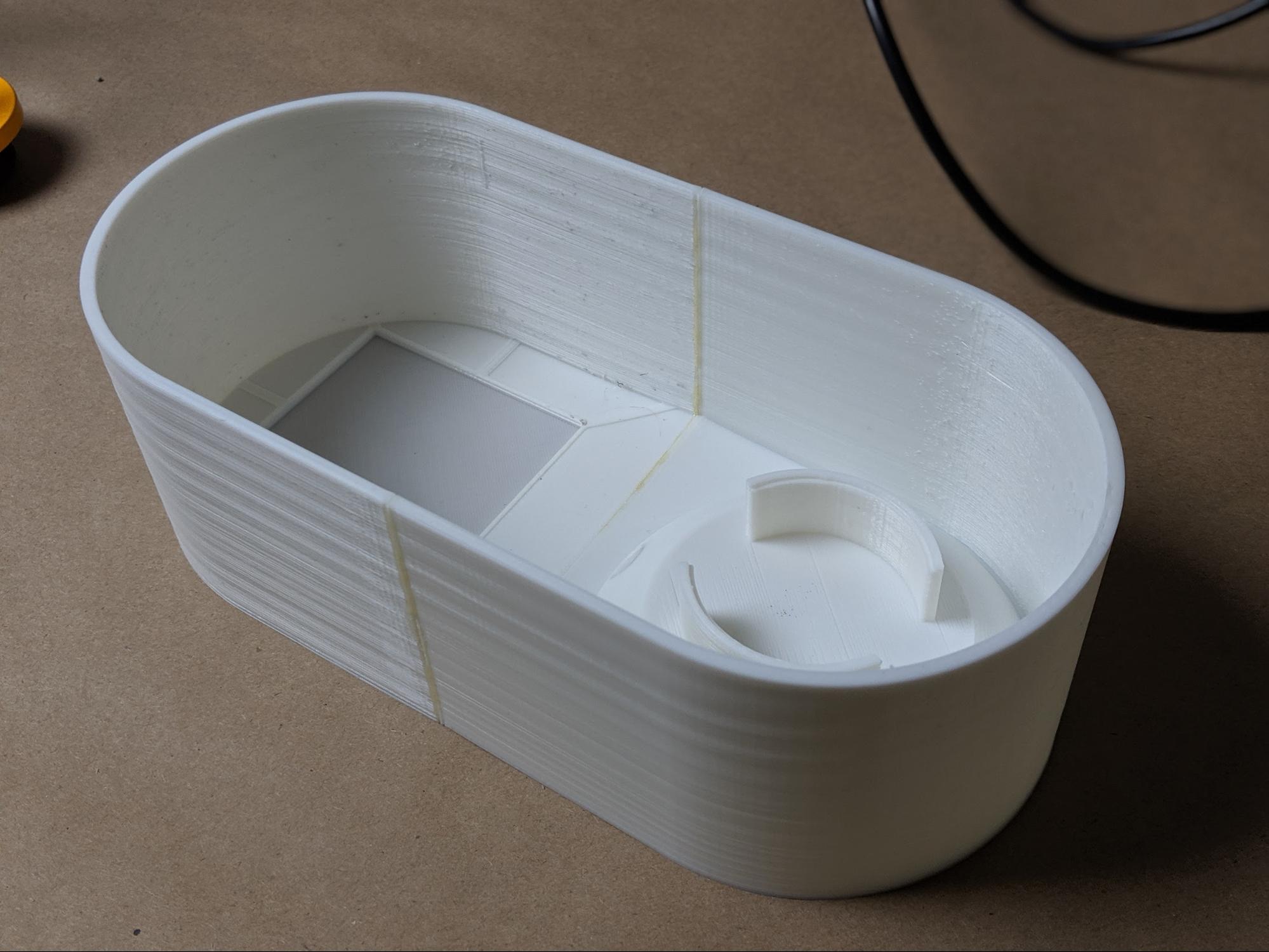
The only significant part remaining is the 3D printed enclosure for the radio. The enclosure is designed for easy 3D printing and just about any 3D printer should be up to the job. If you have a smaller 3D printer, like the Monoprice MP Select Mini I used for this tutorial, you may need to print the enclosure in multiple parts. You can see the dividing line between the sections in the photos below. It does not particularly matter if you need to print the enclosure in parts. Ultimately we will be covering the enclosure in fabric - in the spirit of the Google Home design - so any unsightly seams between parts will be covered.
The outside of the 3D printed enclosure.
On the front of the part is an obvious dished section that will house the Google Home Mini. There is a cutout in the back of the holder that allows the Home Mini to be plugged in through the enclosure.
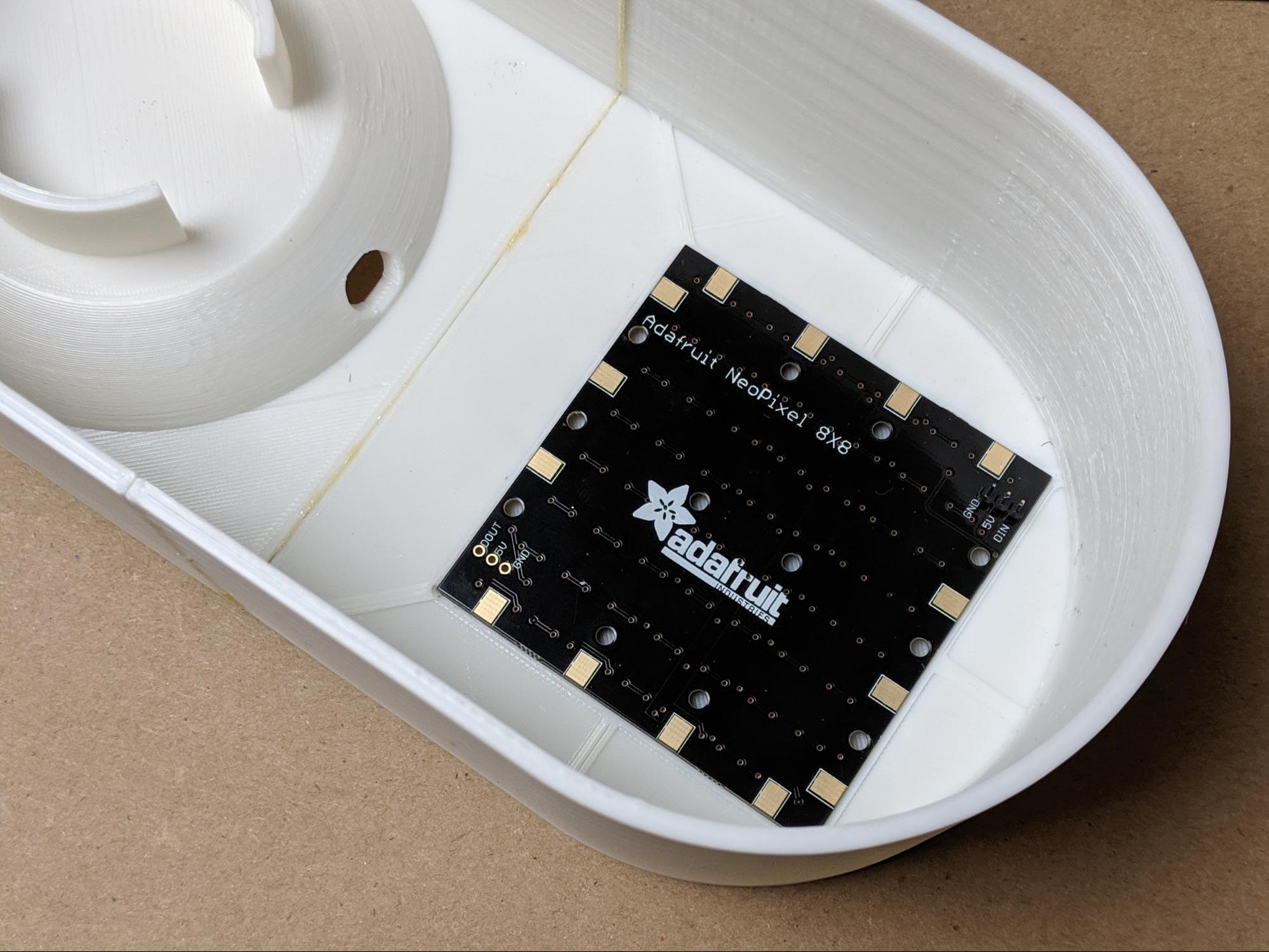
Then, on the opposite side of the enclosure is a square section for the Neopixel LED matrix. You can see from the front of the enclosure that the LED matrix area has a very thin wall that allows the LEDs to shine through the plastic. The LED matrix PCB itself fits into the square section.
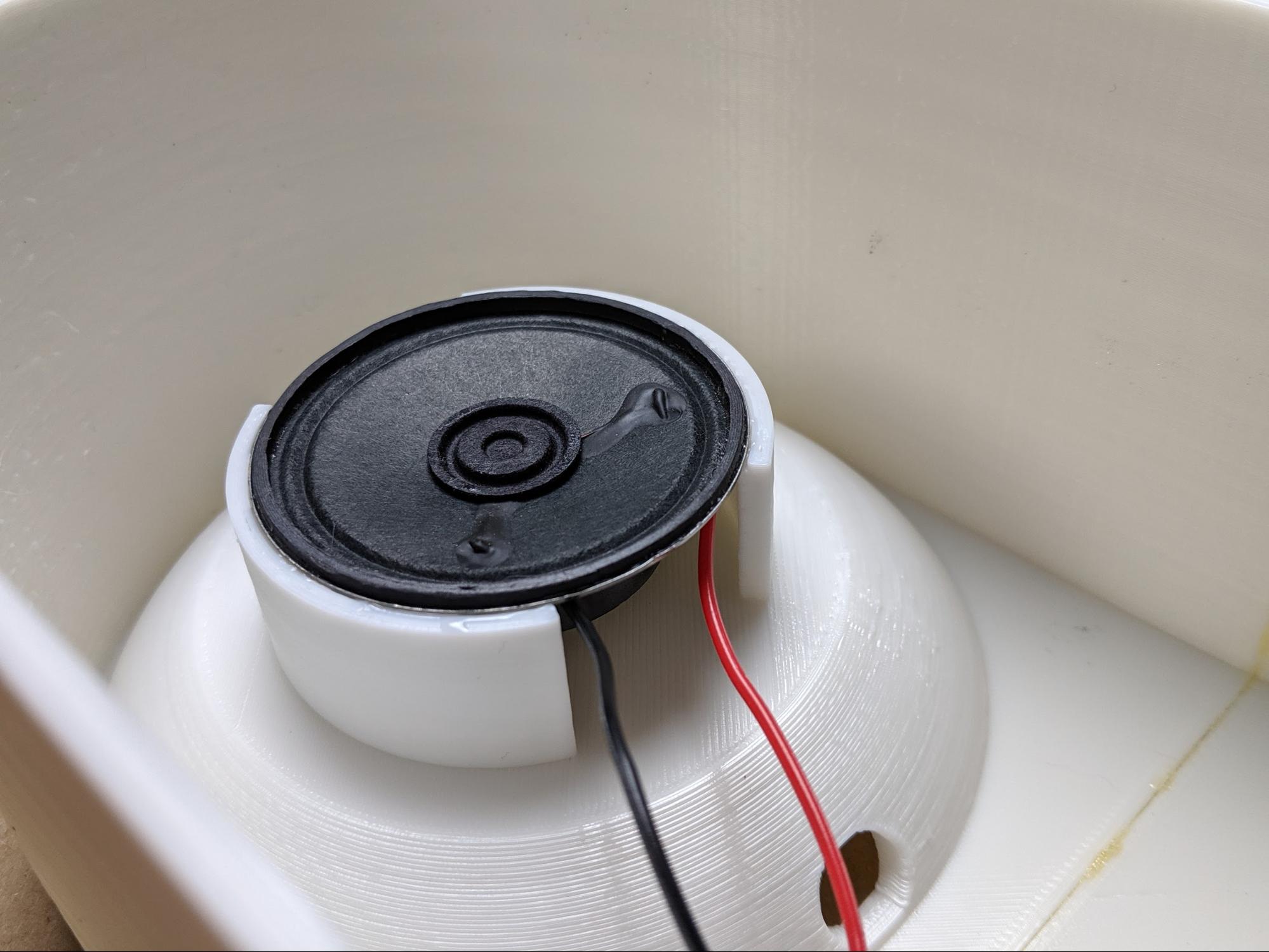
Finally, on the backside of the dished section where the Google Home Mini will live is a set of standoffs. These will hold the radio speaker. Since the Google Home Mini lacks an audio input, we will instead use a separate speaker for the radio. The speaker will mount right behind the Home Mini.
Soldering
To start the build itself, we need to do some prep work in the form of soldering:
- Solder male headers to the Neopixel matrix Din header
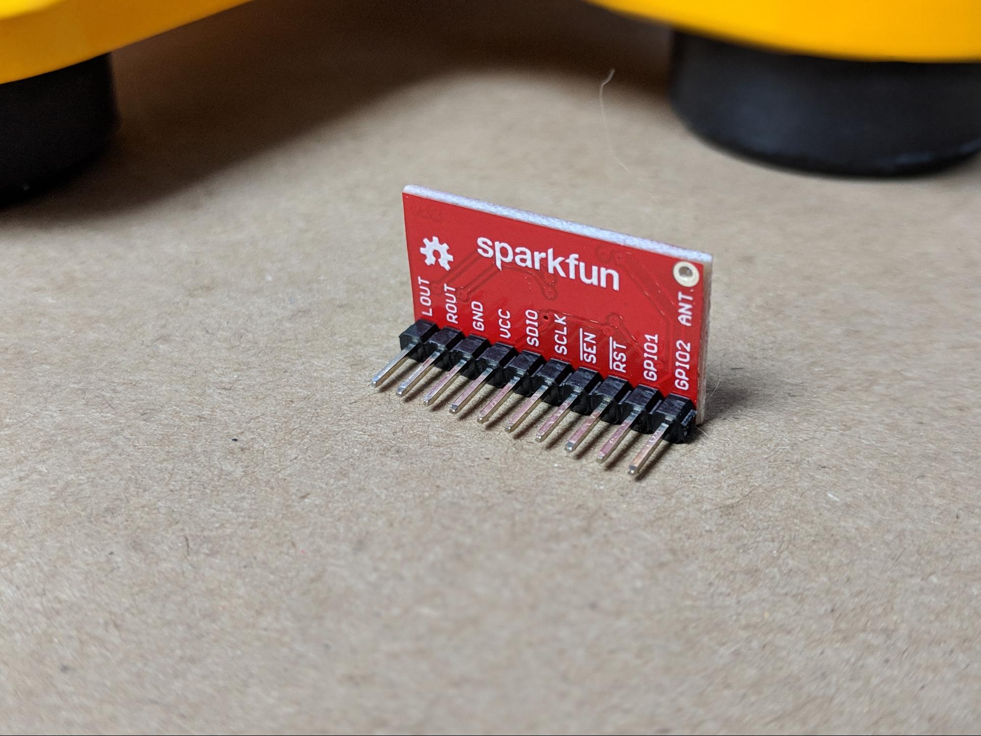
- Solder male headers to the SparkFun FM Basic breakout board
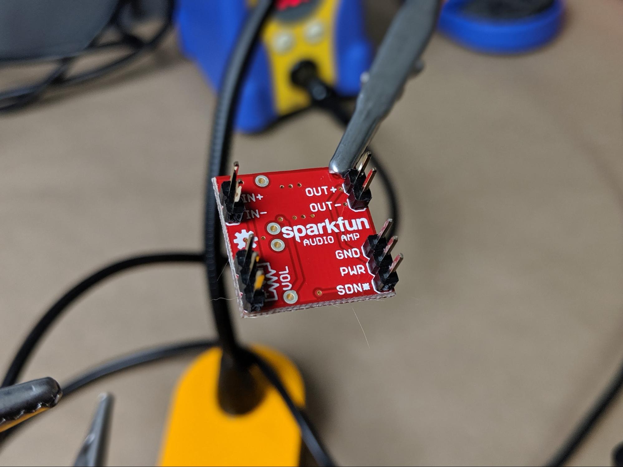
- Solder male headers to the SparkFun Mono Audio amplifier board
- Solder male headers to the Micro USB breakout
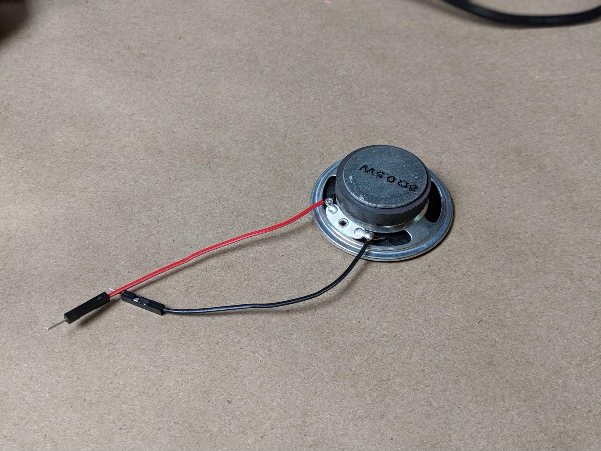
- Solder jumper wires to the speaker
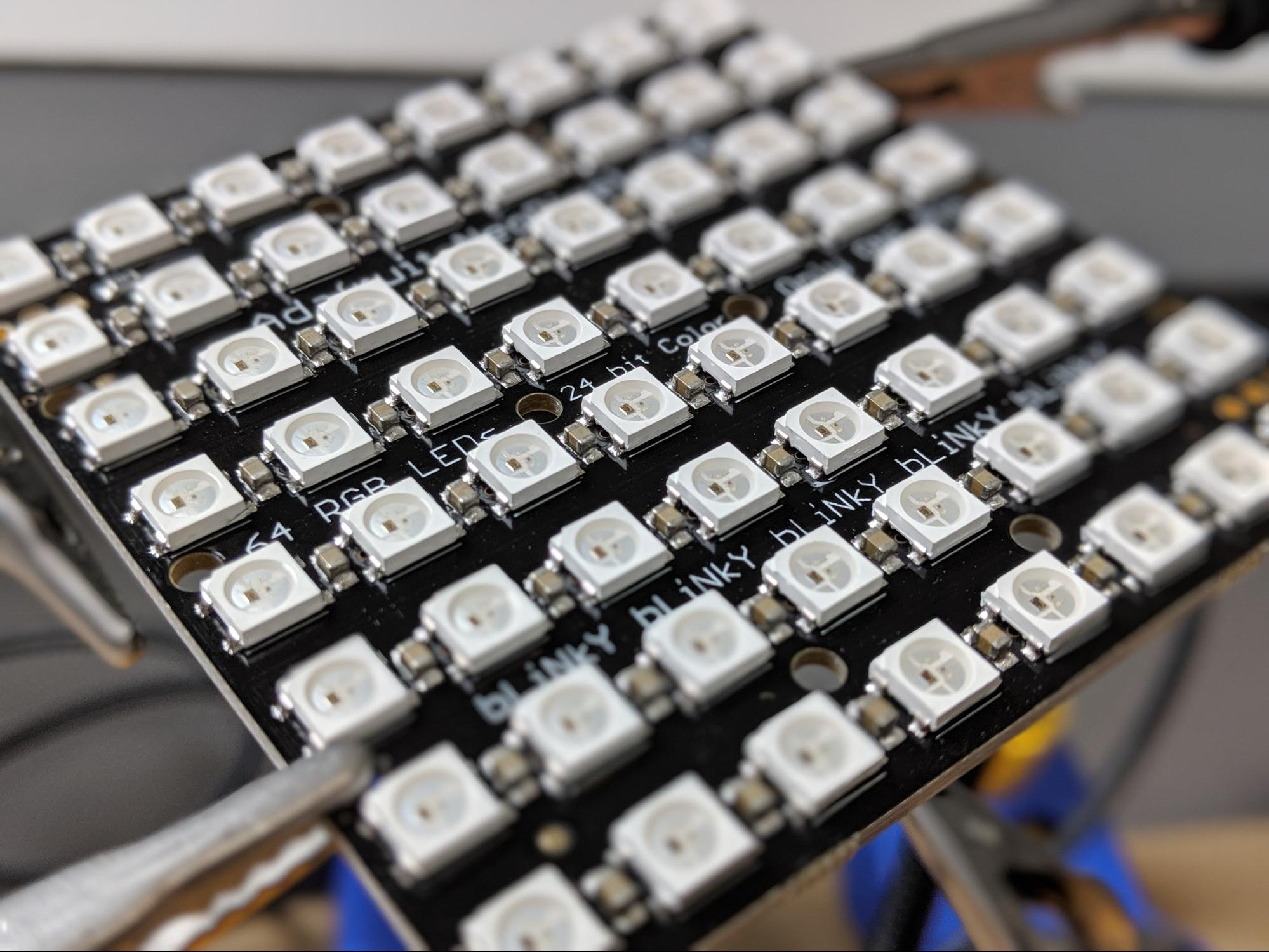
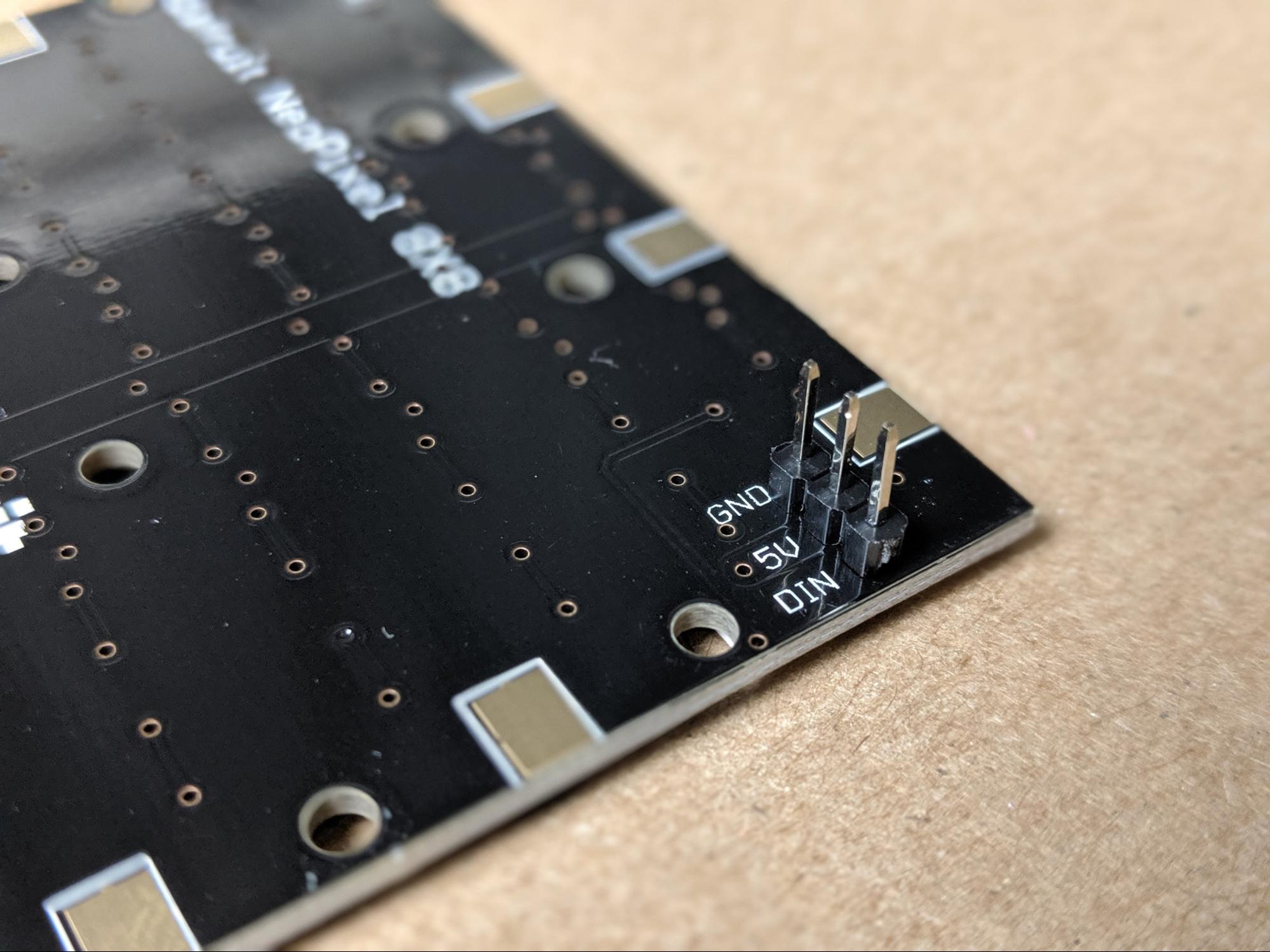
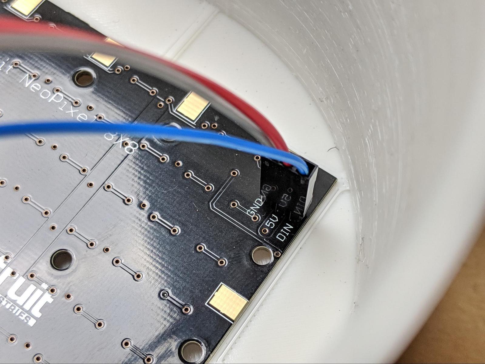
Let’s start with the Neopixel matrix because it is a very beautiful PCB. On the back of the board, you will find two sets of headers. Both have connections for GND and 5V. One set of headers also has a Din pin and the other has a Dout pin. The Dout pin allows multiple Neopixel products to be chained together, which is cool but not something we will be doing in this project. The Din pin is where the matrix receives commands from the Particle Photon. So, solder a set of three male headers to the set of pins with the Din pin.
NeoPixel Matrix 8x8 male header pins
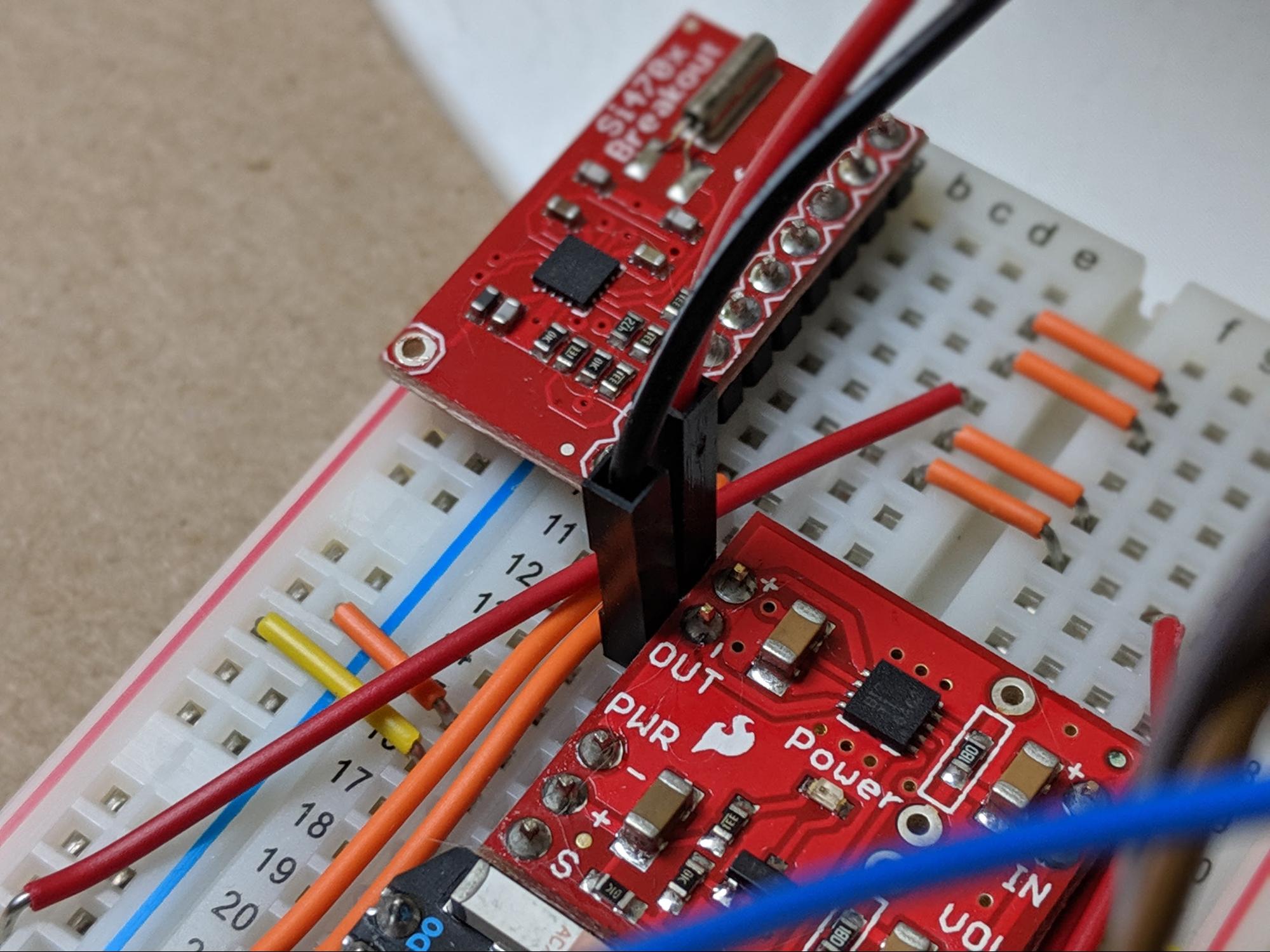
Next up is soldering headers to the two SparkFun breakout boards. Since we will be assembling the circuit on a breadboard, we will solder male headers to the breakout boards. Simply line up the headers carefully to ensure they are straight and solder them on.
Finally, we will need to solder some wires to the speaker that will allow it to be plugged into the breadboard. On the bottom of the speaker, there are two metal contact points near the magnet in the center. Solder a jumper wire terminated by a male pin onto each of these two contact points.
NOTE: Be careful around the magnet because it will attract your soldering iron so be careful not to slip and cause any burns to yourself or your table.
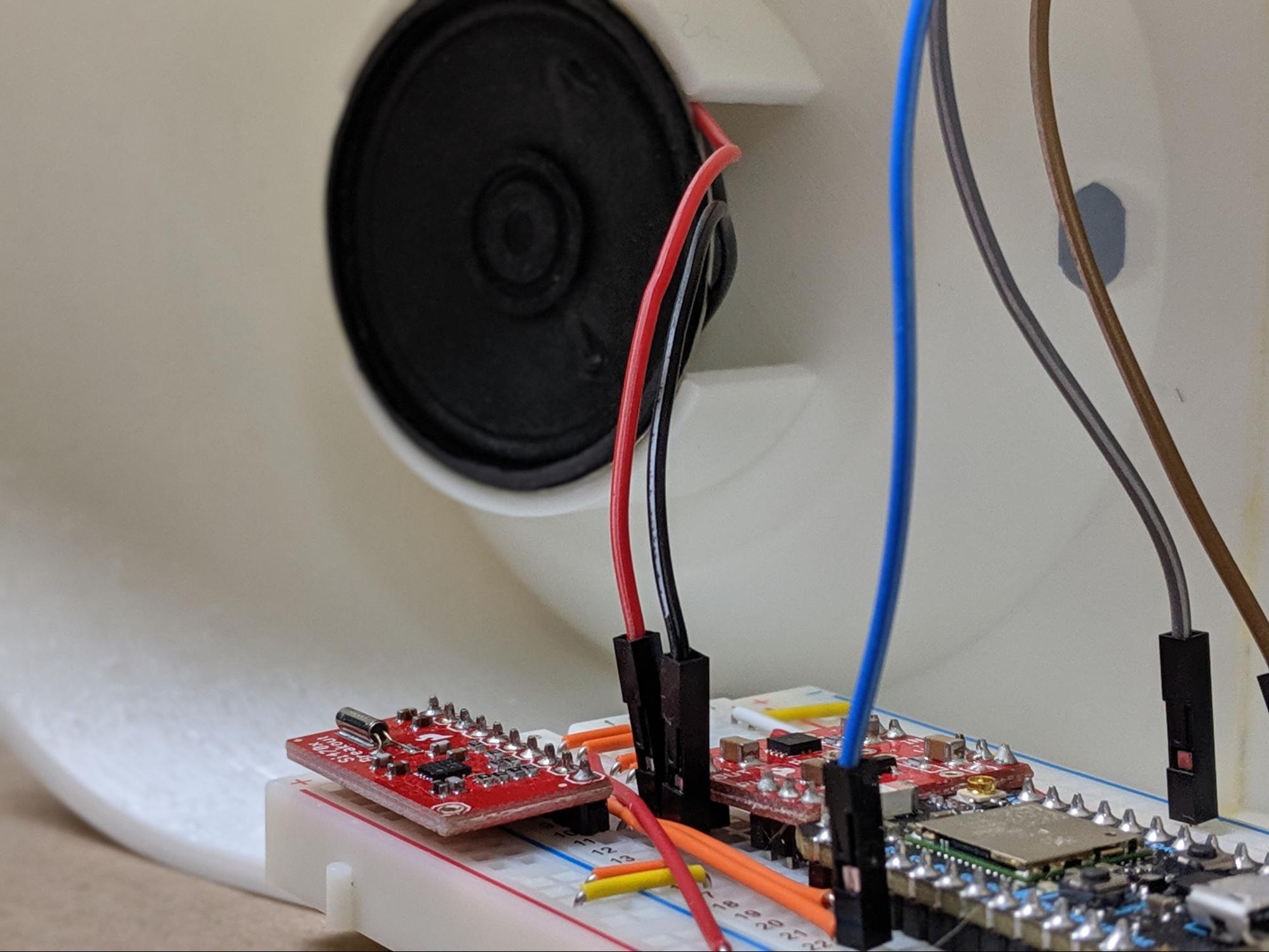
Populate the Breadboard
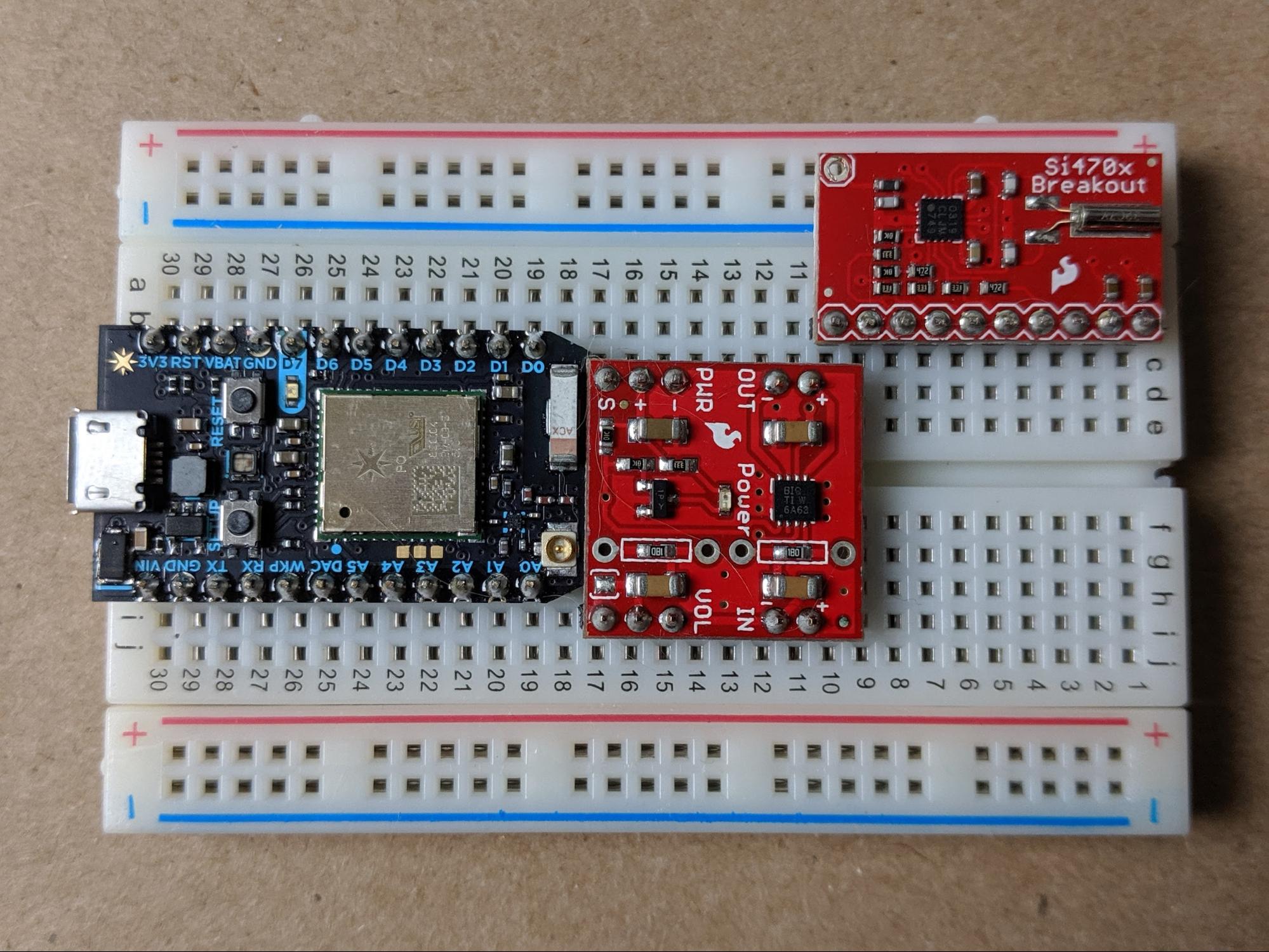
Now that we have pins and wires soldered to all the components, we can begin the build in earnest by placing the Particle Photon and the two SparkFun breakout boards onto the breadboard. This will be the foundation of the project. It will be a tight fit as well.
Starting with the Particle Photon, position the board with the USB port on one side of the breadboard. This will allow the system to be powered via USB. Make certain that the Photon is as close as possible to the edge of the breadboard.
Next up is the audio amplifier breakout board. This board will be positioned immediately next to the Particle Photon. The two boards will probably even overlap a little bit. However, it is important that the audio amplifier and the Photon are right next to each other to make room for the final part, the FM radio receiver. This part will plug into one side of the breadboard. Make sure that none of the three boards are accidentally connected by sharing rows on the breadboard.
All boards populated onto the breadboard.
Wire the Breadboard
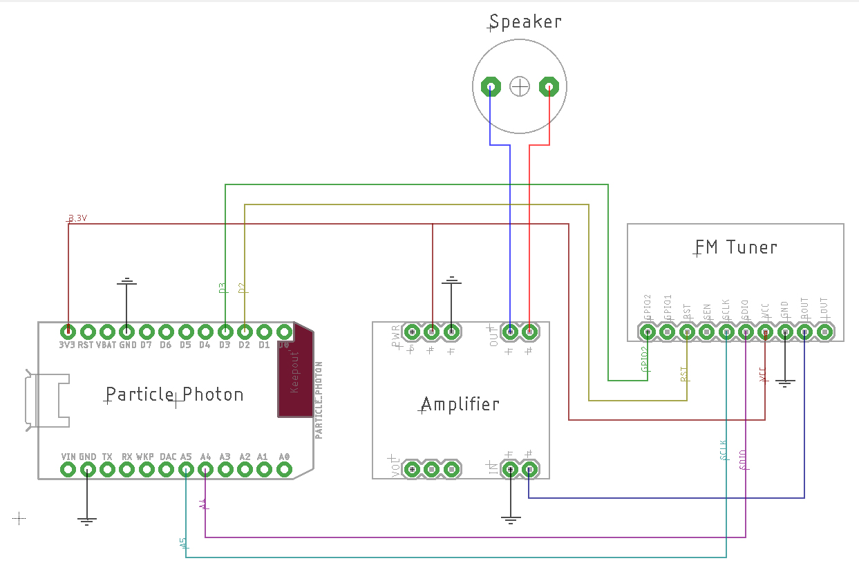
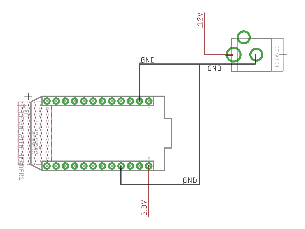
Now that the Particle Photon, FM radio receiver, and audio amplifier are sitting nicely on the breadboard, we can connect these parts. The wiring diagram and tables below show the breadboard connections that are needed to get the system working.
One thing to know about the circuit on the breadboard is how the power rails will work. Both of the ground rails will be connected. However, for the positive rails, one will be 3.3V from the Particle Photon and the other will be 5V from the power supply.
Power Connections
- FM Basic Breakout GND : Breadboard GND rail
- FM Basic Breakout VCC : Breadboard (+) rail
- Amplifier Breakout PWR(+) : Breadboard (+) rail
- Amplifier Breakout PWR(-) : Breadboard GND rail
- Photon 3.3V pin : Breadboard (+) rail
- Photon GND pins (both sides) : Breadboard GND rails (both sides)
Audio Connections
- FM Basic Breakout Rout : Amplifier Breakout IN(+)
- Amplifier Breakout IN(-) : Breadboard GND rail
Control Connections
- FM Basic Breakout SDIO : Photon A4
- FM Basic Breakout SCLK : Photon A5
- FM Basic Breakout RST : Photon D2
- FM Basic Breakout GPIO2 : Photon D3
The full radio schematic.
Install the LED Matrix
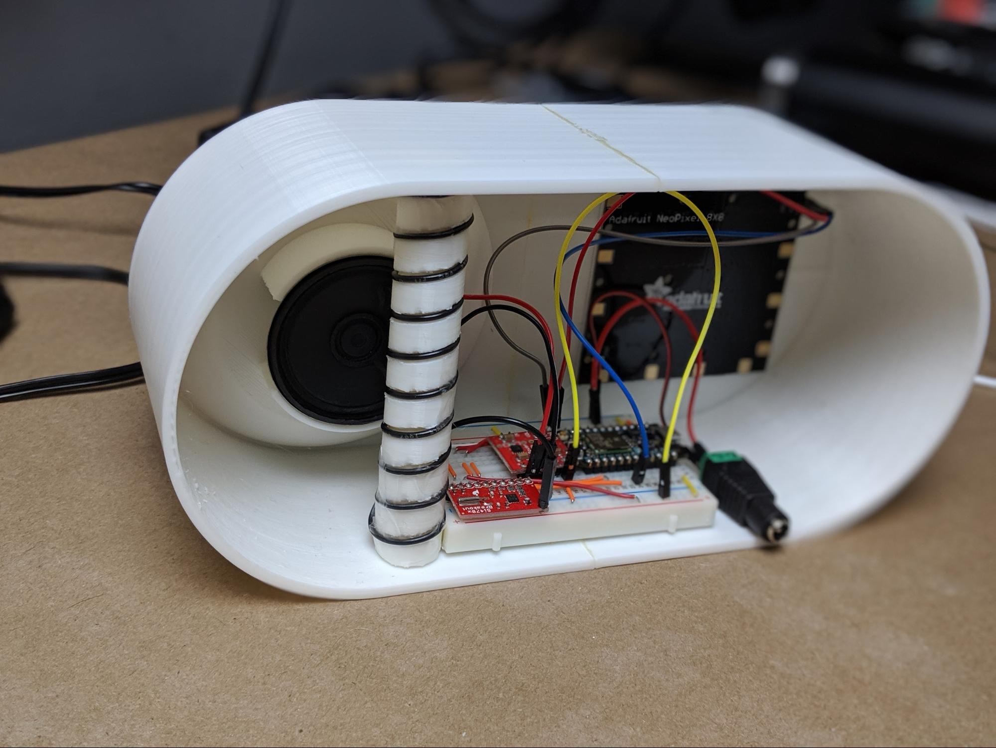
The next step is to install the LED matrix into the 3D printed enclosure. On the inside of the enclosure, as mentioned previously, there is a square area with a very thin wall allowing the light from the Neopixels to shine through the enclosure and the fabric that will eventually cover the entire project. To install the LED matrix, simply use a bit of force to press the PCB into the square cutout.
Add the Speaker
Similarly, we need to install the speaker into the enclosure as well. The speaker installs on the standoffs on the backside of the dished area where the Google Home Mini will eventually go. If you take a close look at these stands, you will notice that the inside of the circular shape is not as tall as the outside. This allows the speaker to fit perfectly into the standoffs.
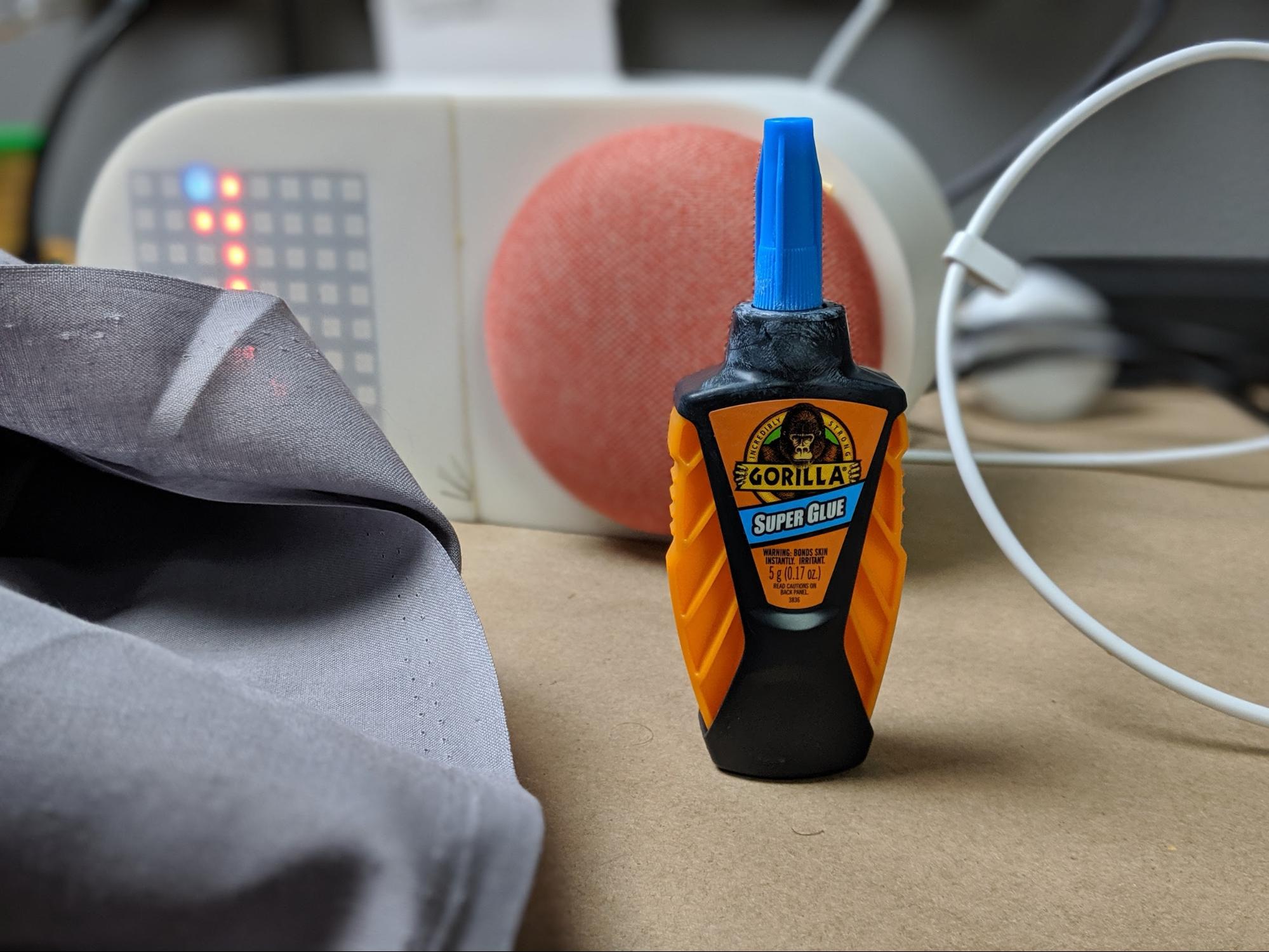
Using a bit of glue, secure the speaker in place on the standoffs. I used some Gorilla clear glue, but just about any kind of glue will work fine. The speaker is not heavy.
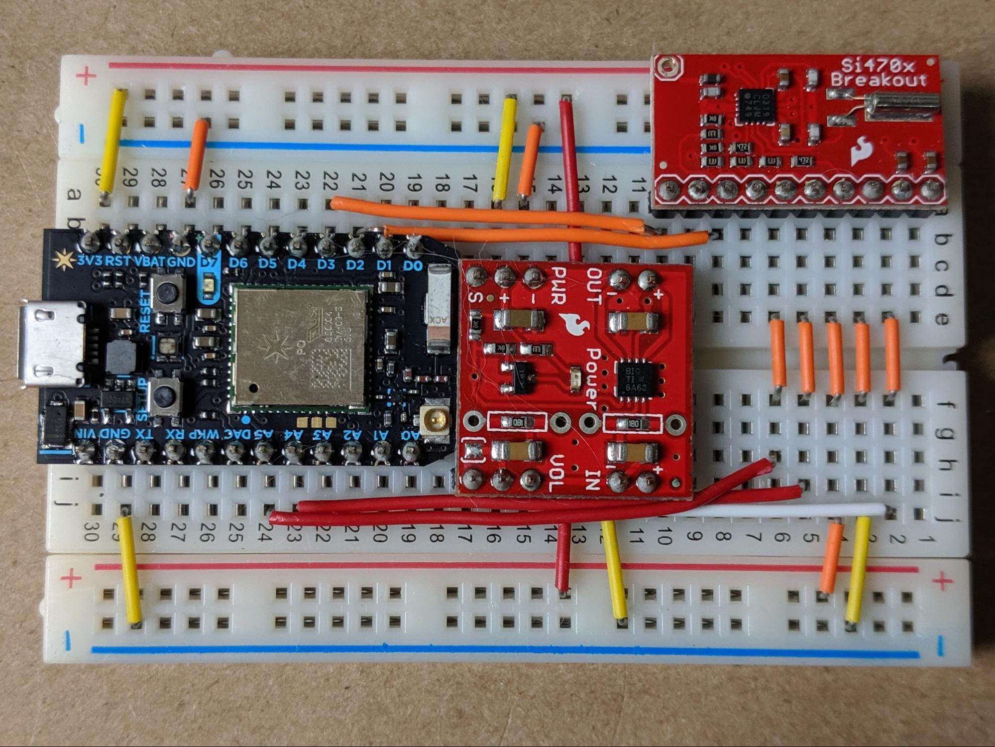
Wire the LED Matrix to the Breadboard
At this point, we have all of the individual hardware we need to complete the project. The next phase is to bring it all together and make the last couple of electrical connections, starting with the LED matrix.
The matrix has three connections: GND, 5V, and Din. One thing to note here right away is that, unlike all the other components we’ve already placed and wired on the breadboard, the LED matrix operates off 5V, not 3.3V. Therefore, the LED matrix will be powered directly from the power supply by plugging directly into the 5V rail on the breadboard.
Connect the GND pin on the LED matrix to one of the GND rails on the breadboard as well. Connect the 5V pin on the LED matrix to the 5V rail on the breadboard. And finally, connect the Din pin on the LED matrix to pin D4 on the Particle Photon.
Connect the Speaker
The speaker will also need to be connected to the audio amplifier breakout board via the breadboard. This is a simple process. On the amplifier breakout board, there are two connections labeled Out. The wires we soldered onto the speaker simply plug into these two pins.
Connect the Power Supply
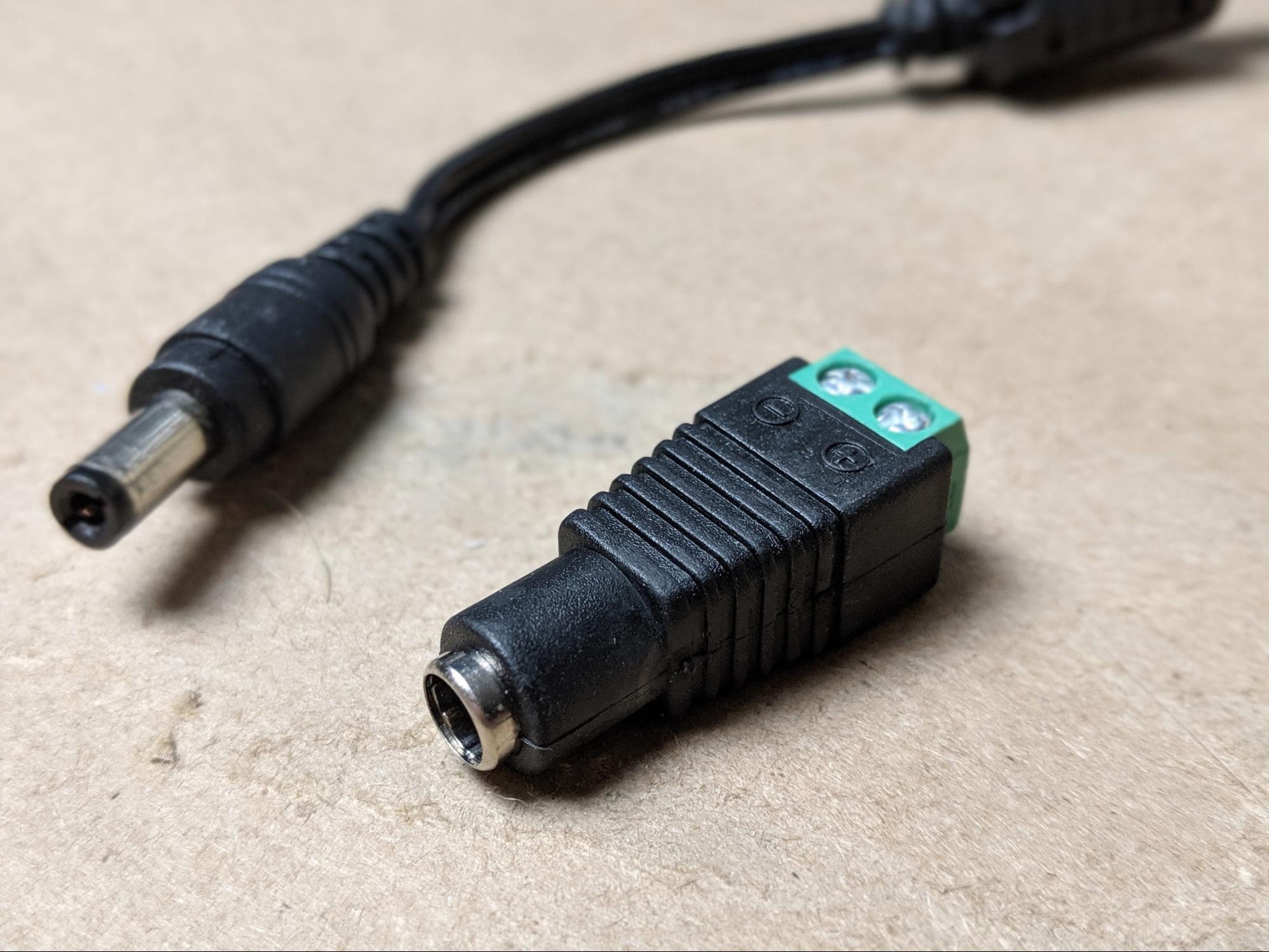
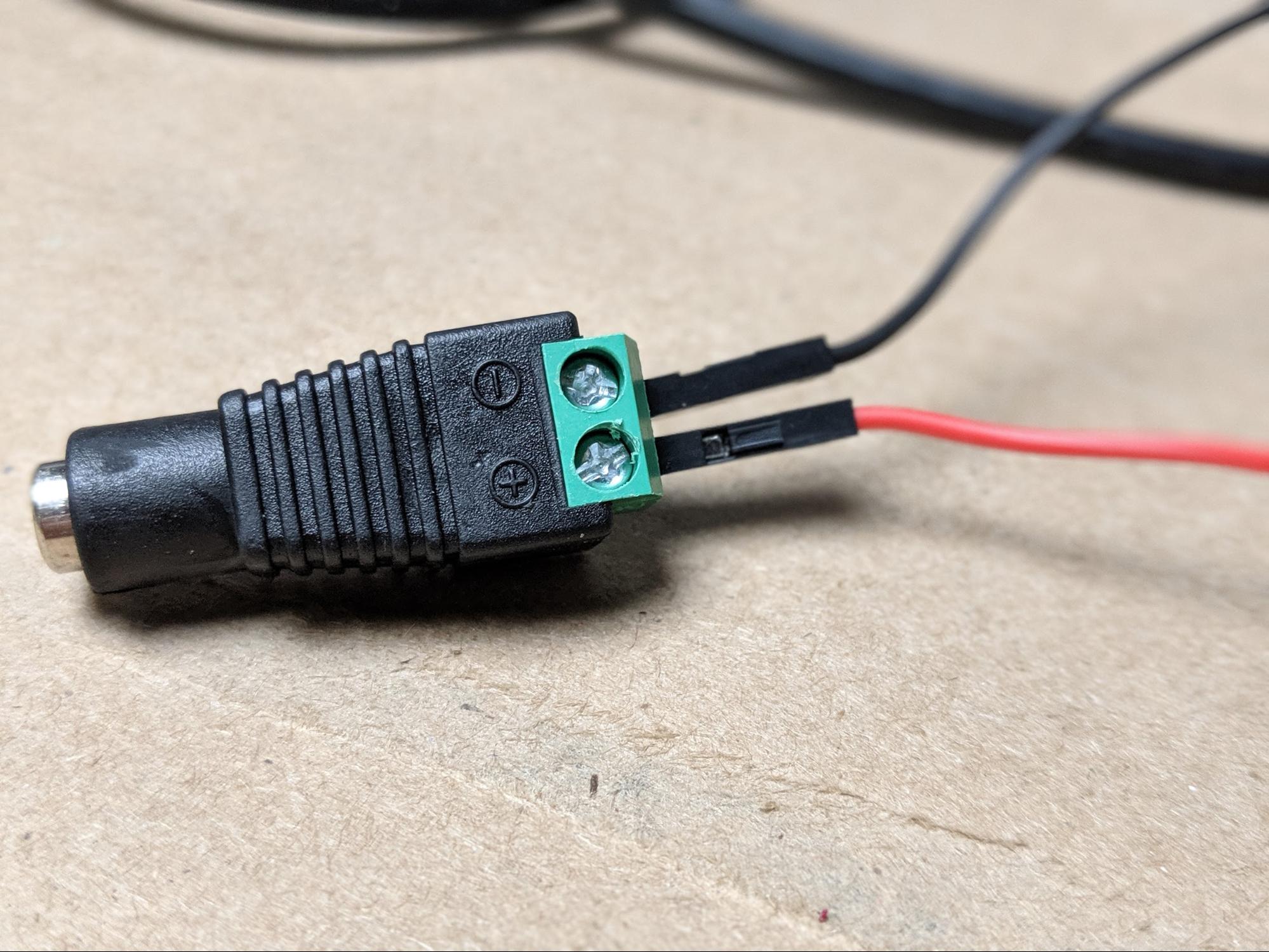
We've mentioned the power supply several times at this point and now we will connect it to the breadboard. The power supply is terminated by a 2.1mm barrel jack so we will use an adapter to allow the power supply to be connected to the breadboard easily.
First of all, attach one red and one black jumper cables to the screw terminals. Like normal, the red wire connects to the positive screw on the barrel jack connector and the black wire connects to the negative pin.
Then, connect the black negative wire to one of the GND rails on the breadboard. The red positive wire connects to the 5V rail; DO NOT connect this wire to the rail with the 3.3V from the Particle Photon or you will destroy the microcontroller.
Flash the Firmware
With power connected to the Particle Photon from the power supply, the next step is to flash the firmware onto the board using Particle’s online IDE.
This article assumes that you’ve already claimed the Particle Photon, a process covered in a previous post about the Particle Boron and by Particle’s own getting started guide.
So, first of all, copy/paste the code into your Particle IDE. You can find the full code as a downloadable file at the end of this article.
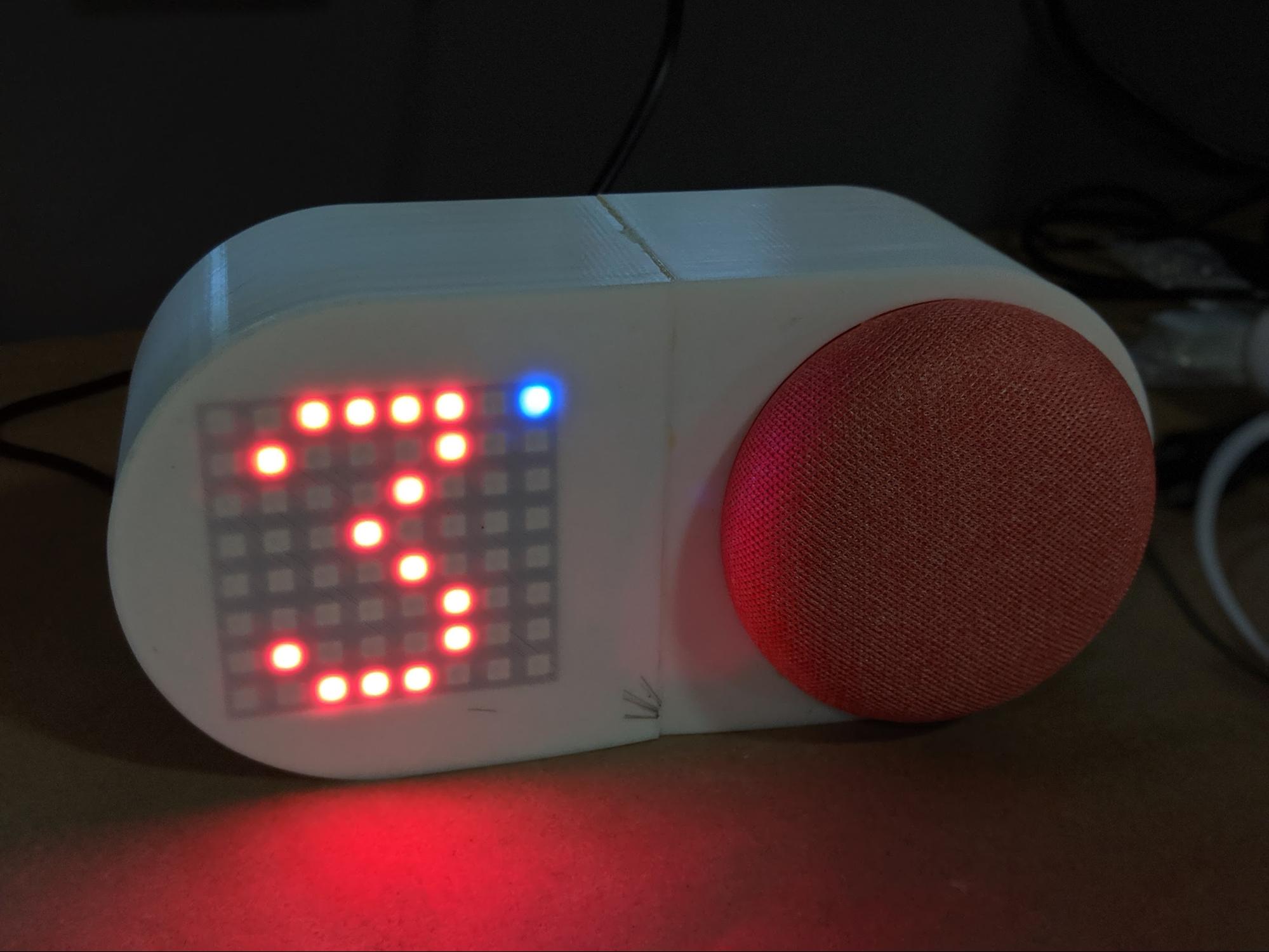
Then, with your Particle Photon selected, flash the firmware onto the board. When the process is complete, you should see a clock appear on the LED display. The clock displays the current hour in the center, with a minute “hand” circling the outside of the display.
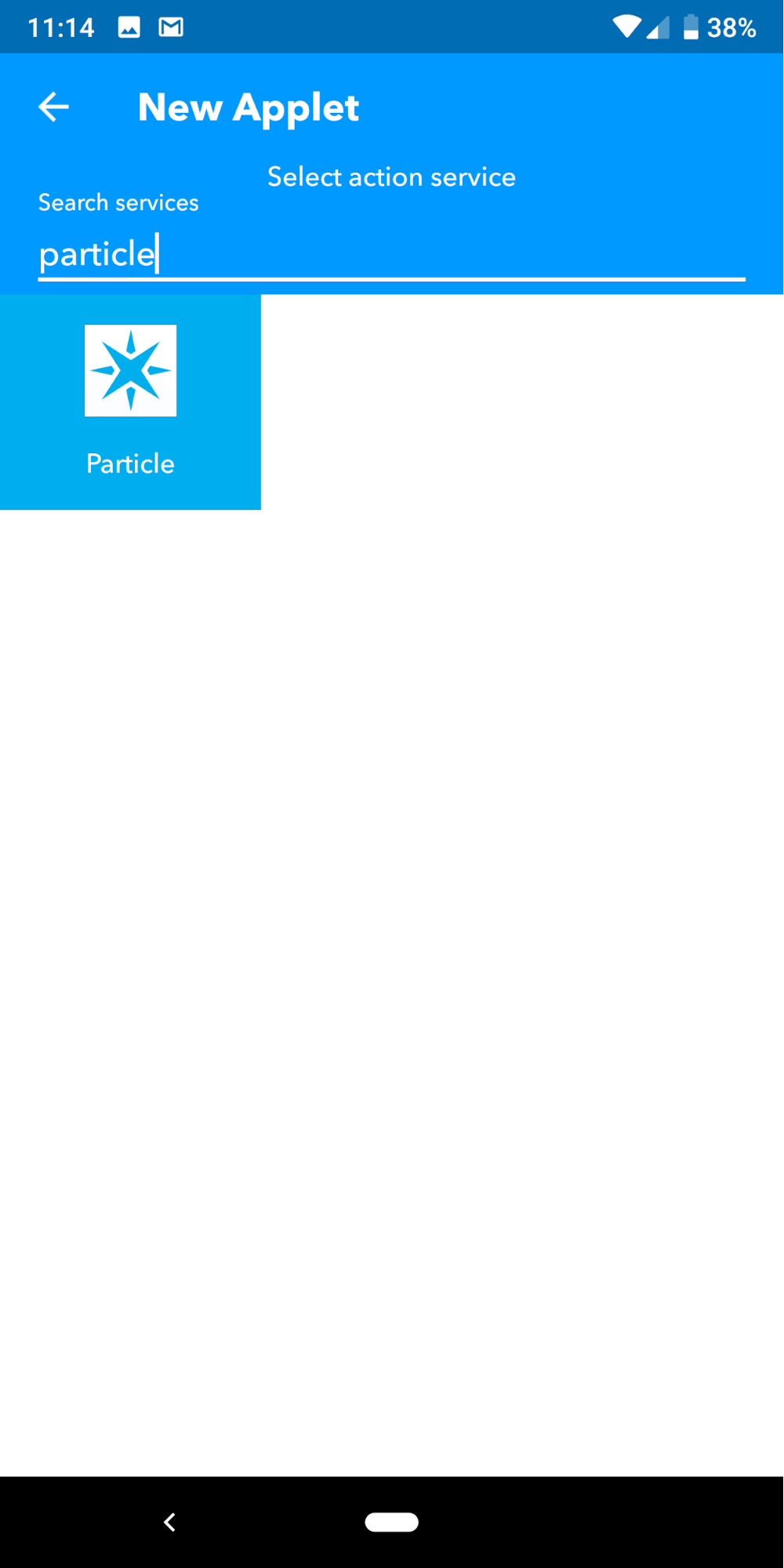
Create your IFTTT Recipes
So, right now we have a functioning radio complete with a WiFi connection provided by the Particle Photon. We also have a Google Home Mini. There is one final part we will need to link these two basic parts. We will use IFTTT to link Google Assistant commands to functions in the code running on the Particle Photon.
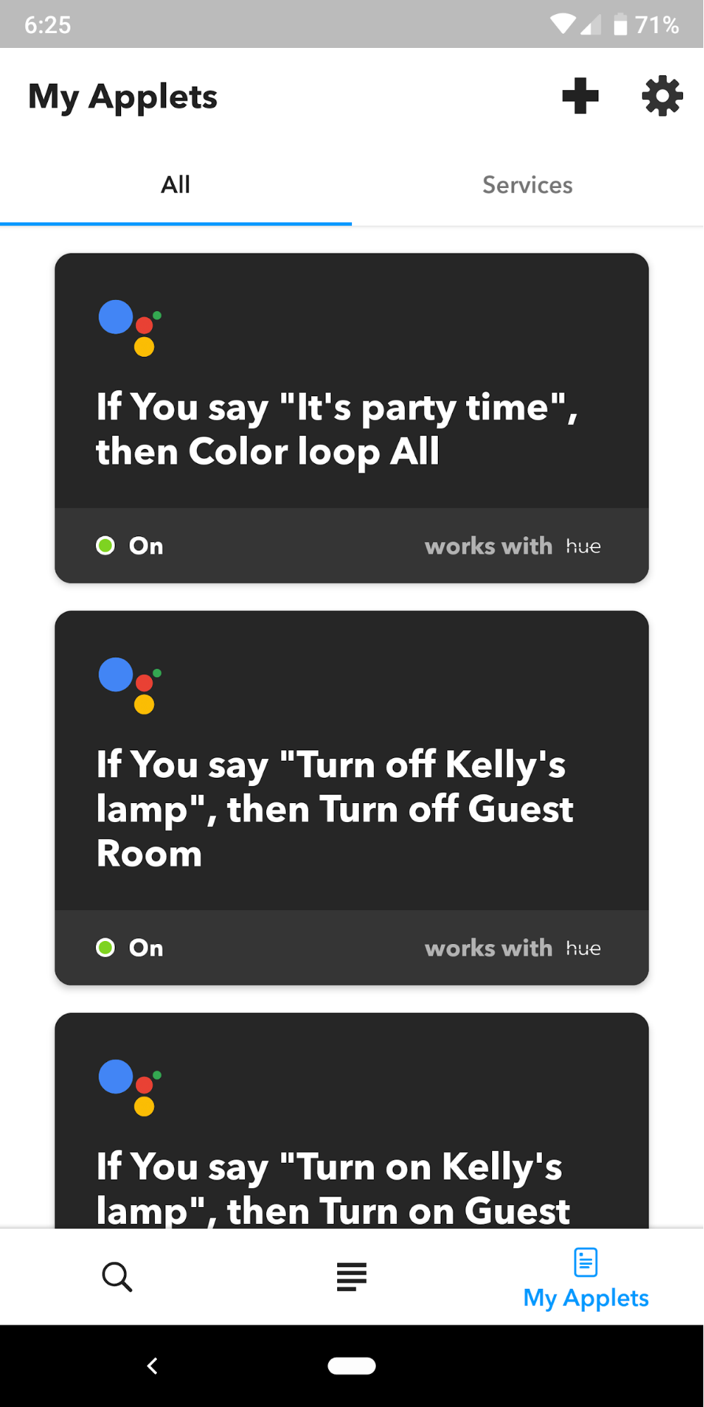
Assuming you have the IFTTT app installed on your phone, open the app and head to the My Applets tab to get started. From there, click the + button in the upper-right corner to create a new applet.
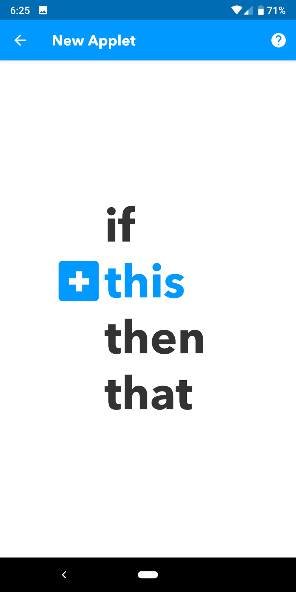
We will start creating the applet by selecting the this portion of the recipe.
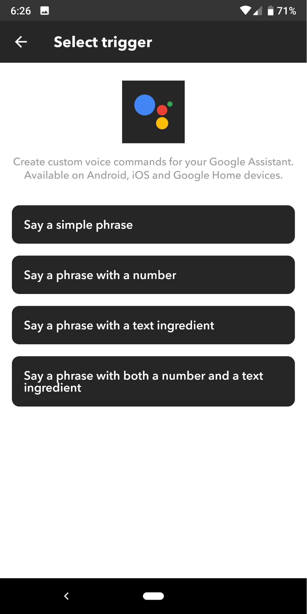
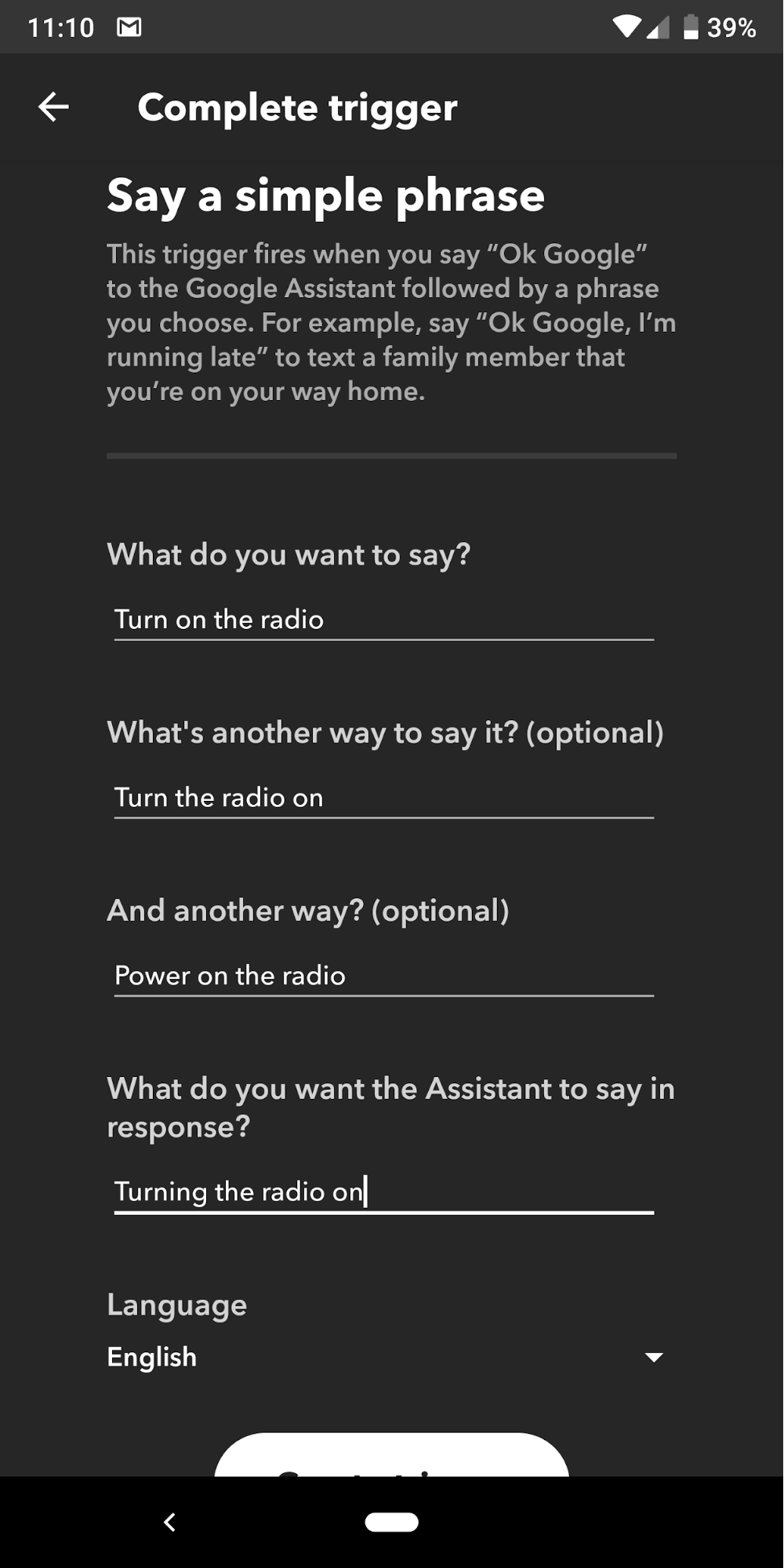
To trigger the applet, we will use the Google Assistant. In this case, we will use a “Say a simple phrase” trigger.
We will be creating these different commands:
- "Ok, Google. Turn on the radio."
- "Ok, Google. Seek up."
- "Ok, Google. Seek down."
- "Ok, Google. Turn off the radio."
So we will need to repeat this whole process a total of four times. For each phrase, you should input the phrase itself, along with some other ways you might ask Google Assistant to perform the same action.
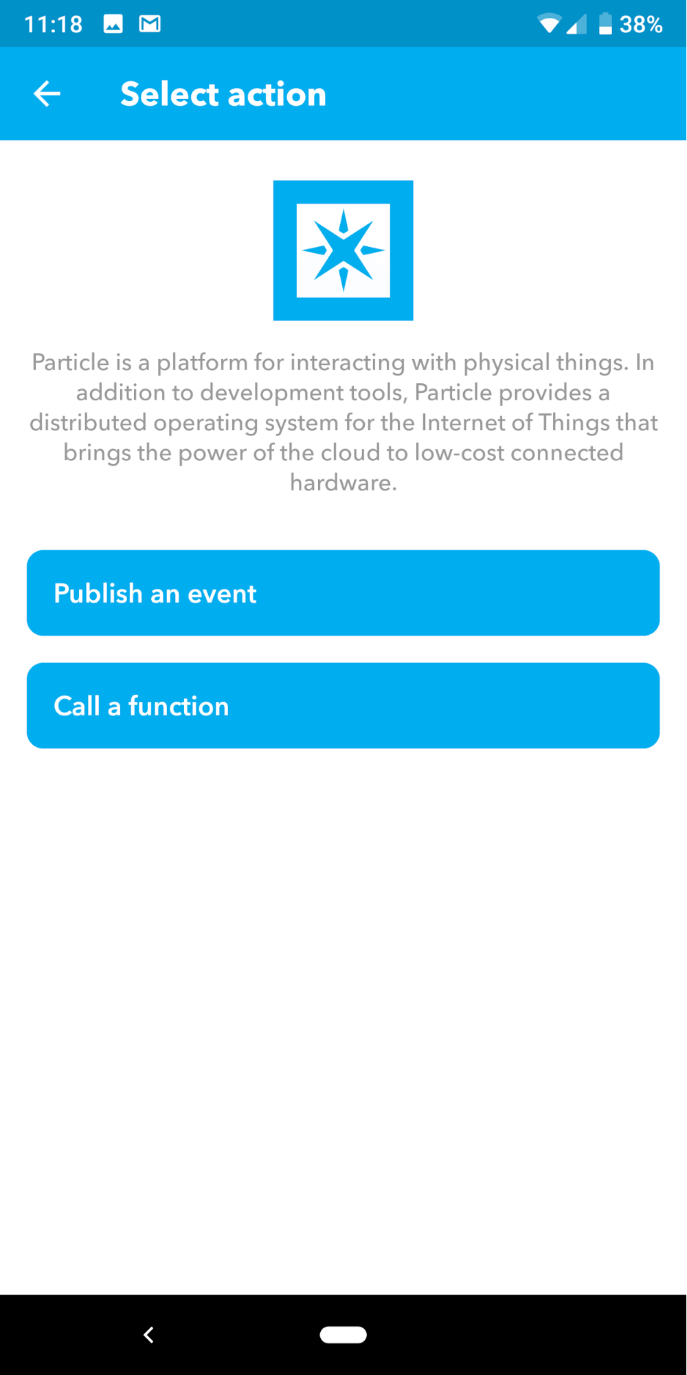
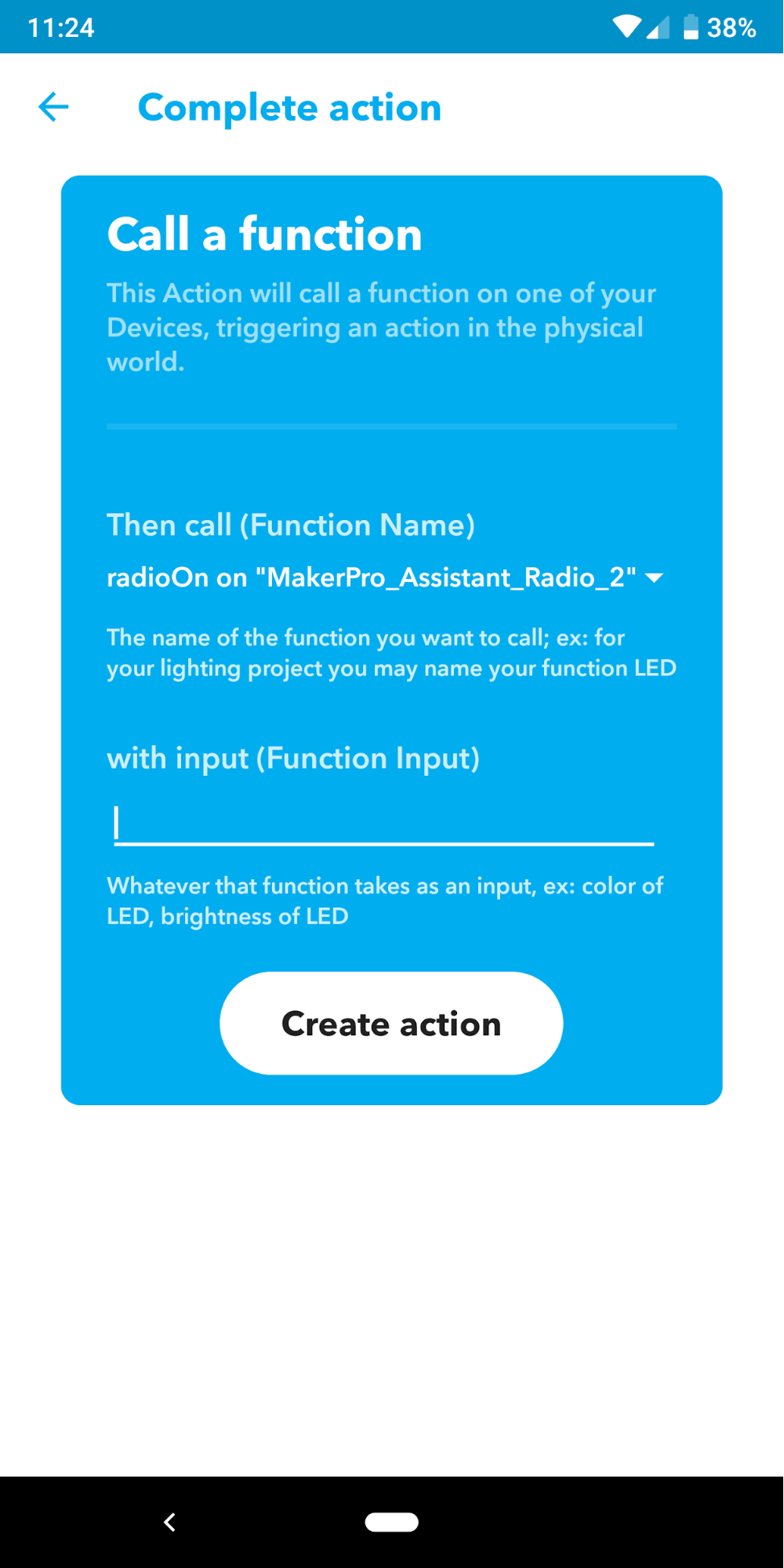
Now onto the that portion of the IFTTT recipe. Here we will select Particle as the provider.
We will choose the option to “Call a function” in response to the trigger.
From the dropdown menu, select the function that corresponds to the phrase you input into the trigger earlier.
Complete the process by tapping the Finish button.
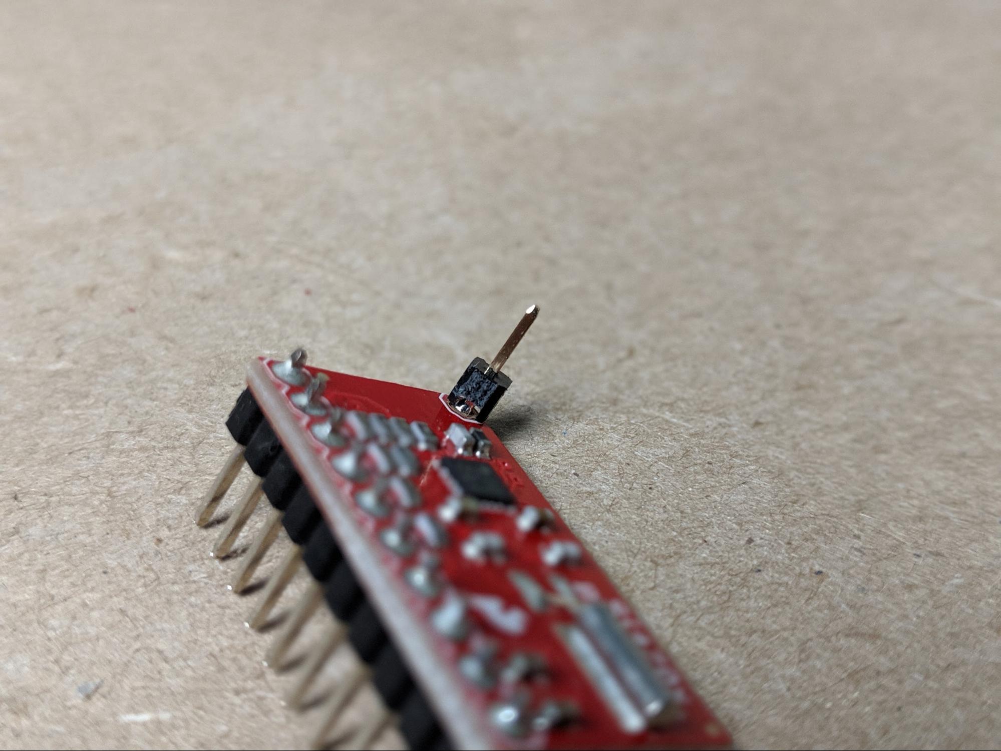
Add the (Optional) Antenna
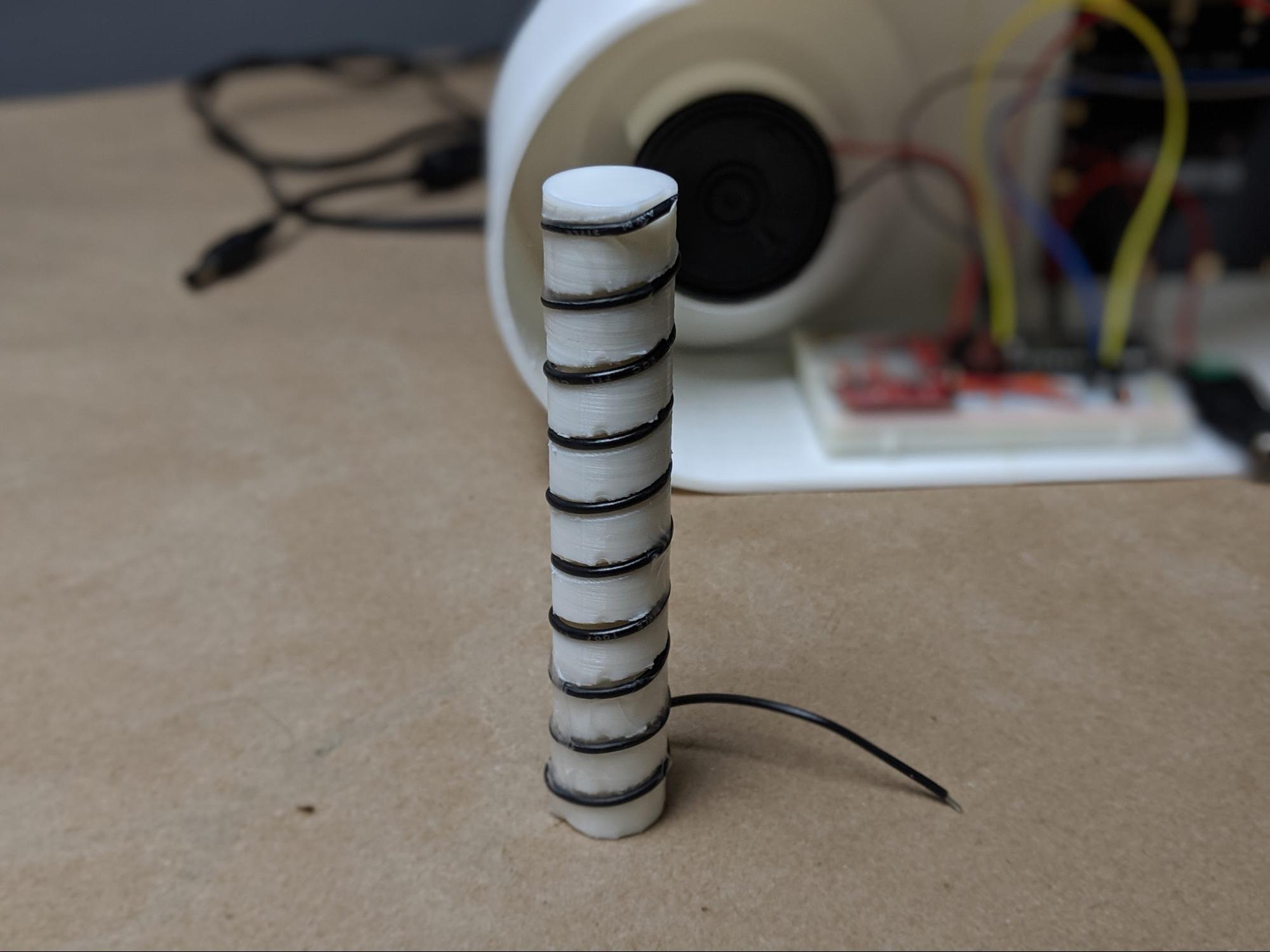
Depending upon the strength of the radio signal in your area, you may need to add an antenna to the Si4703 FM Tuner Basic Breakout for it to receive a clear signal. The antenna connects to the lonely pin in the upper corner of the breakout PCB. So, the first step is to solder a male header pin onto this pad.
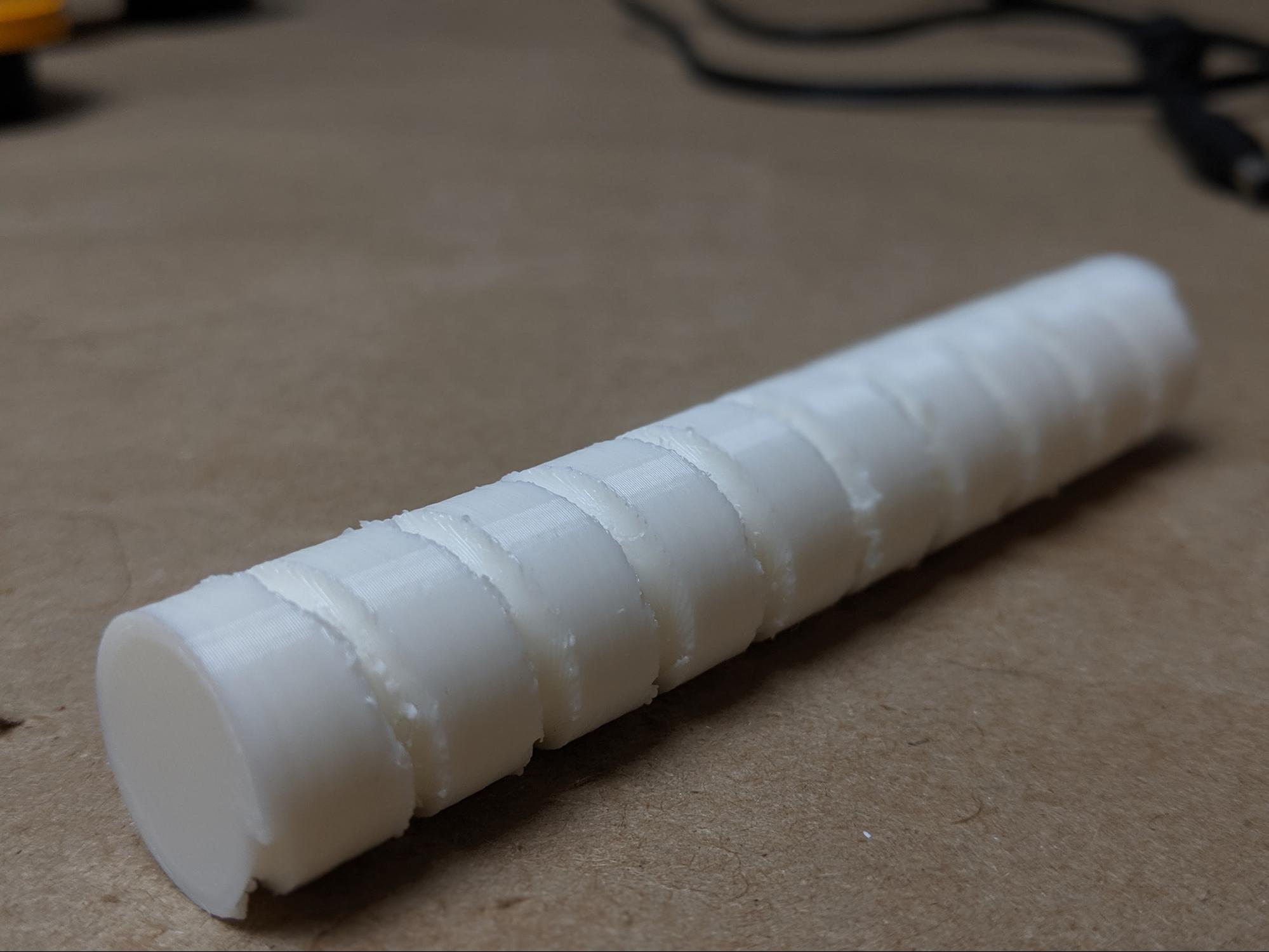
Then we need to build the antenna itself. To do this, the first step is to fire back up your 3D printer. The antenna is made from a cylinder that stands the height of the enclosure. We will wrap wire around the cylinder to form the antenna itself. So first, print the antenna cylinder.
Then, using a length of wire (basically, any wire will work just fine) wrap the 3D printed cylinder with wire, following the spiral groove around the part. On one end of the cylinder, you will need to leave a couple inches of extra wire for attaching the antenna to the FM Tuner Basic Breakout pin we soldered on earlier. On the opposite end of the 3D printed part, the wire can be cut flush.
Finally, to install the antenna, first place the part inside the radio enclosure. The exact fit of the part will make a kind of friction fit inside the radio. Then, connect the spirling wire to the FM Tuner Basic Breakout board.
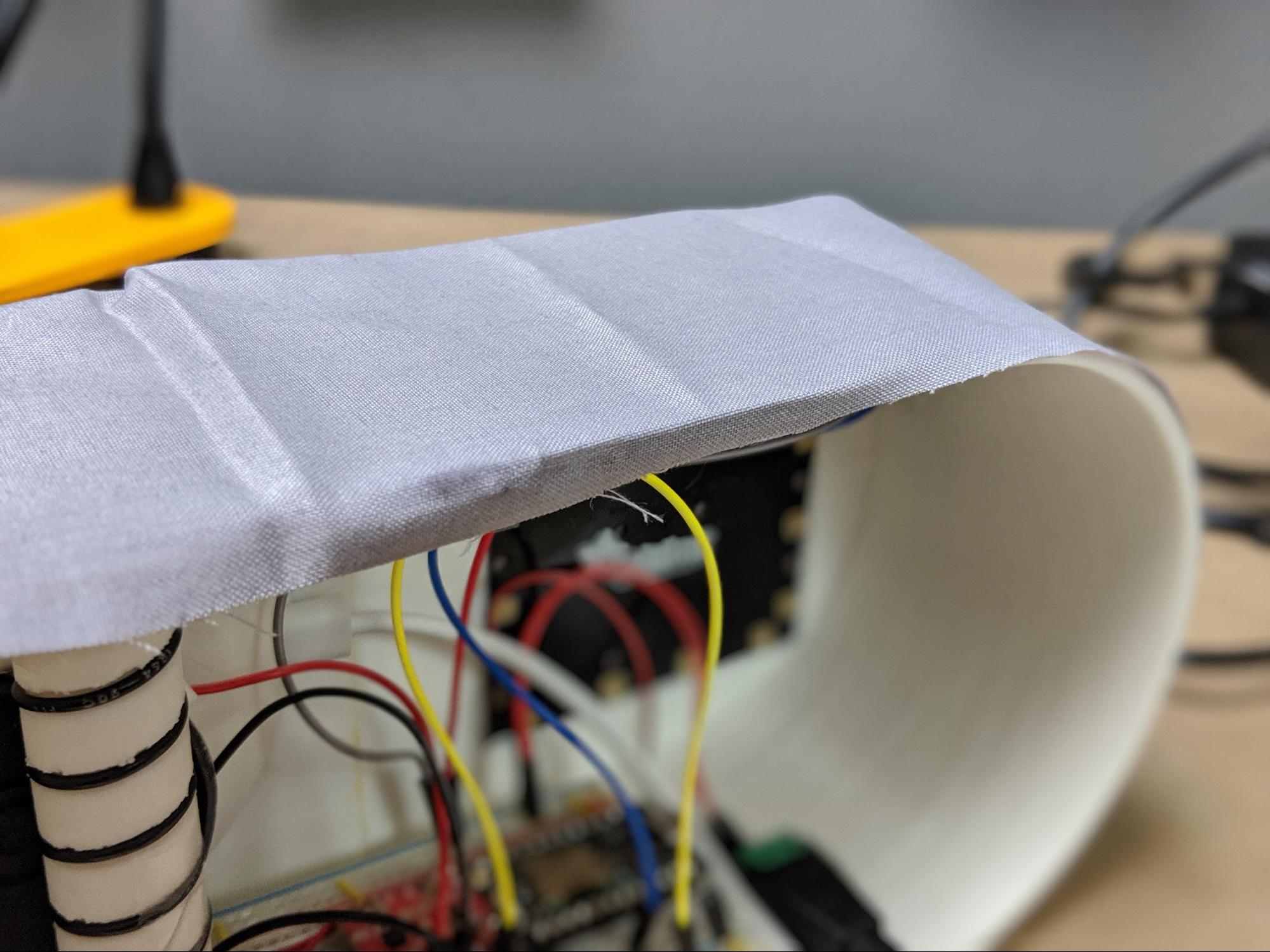
Wrap it in (Optional) Fabric
The final, finishing touch you can choose to do for your radio will be to wrap the enclosure in fabric. This step is fairly simple and involves using super glue to attach a fabric covering to the radio enclosure.
First, you will need to cut a rectangular piece of fabric about 270mm x 280mm. Then, to attach the fabric, we will use super glue on the back edge of the enclosure. I like to start in the middle. Simply place a bit of super glue onto the back of the enclosure, and stick the fabric to it.
Then, work your way around the enclosure until the fabric wraps the entire project.