Maker Pro
Maker Pro

Zener Diode - I feel terrible!

Hi. I read the post about finding the correct part numbers but after using Google and several search data sheets I cannot for the life of me find the p/n for a Zener.

I have a number Z327A and have searched even using the * after a part number etc etc.

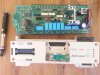
Anyways I attached a pic. Please help!
 

Attachments

  • Zener Stumped.jpg
    Zener Stumped.jpg
    108.6 KB · Views: 117
A27 or 27A. Honestly I am a technician but electronics is new to me after only a couple of years of playing around with them.

I have found one/several types. And the ones that match in the visual sense dont match the power supply I am repairing.

My second trade was in aircraft engineering. There were pretty much the same part numbers for everything - or a very descriptive alternate.

Gee. I can even do a search for A27 and get a picture of a Thai girl.

Ok fair enough I will study Zeners and how they are rated in more depth.

Regards Boyd
 

Harald Kapp

Moderator
Moderator
That's the schematics number.... Not the component part number
At first I thought so, too. But have a closer look at other components. The designators typically have 2 parts:
  • reference designation from schematic (e.g. R3, DZ1, ...)
  • value in parentheses (1.2K, Z327A, ...)
Unfortunately I haven't been able to find a Z327A (or 327A) zener diode either.

For whatever it may be worth, I found these links:
http://www.weisd.com/test/GenericParts_WEISD_view.php?editid1=309-327-802

http://shop.evilmadscientist.com/productsmenu/partsmenu/327-zener :D
 

(*steve*)

¡sǝpodᴉʇuɐ ǝɥʇ ɹɐǝɥd
Moderator
I found one zener, but it was a stud mount 2N3327A or similar, and clearly not whar goes there.

Do you have the original part? Perhaps it has useful markings?
 
How did you get from a relay board . . . . . all the ways to this . . . . and not even give this equipment's Brand and Model number ?
Haha. Sorry! I managed to purchase a Mitsubushi F1-30 (from memory) which is a programmable controller for a pneumatic bank. It came with a large 24vdc thransformer which I immediately thought had to be connected to the 24vdc on the controller.

I was incorrect. The terminals I had fed into were the boards output to power sensors. So after inputting power into an output I blew a section of the board including TR1 and removed the Zener as well for access. Oh and popped a cap.

The relay bank is an addition to this.

I will double check the board number. But all the part numbers or specs are on the board except for this zener.
 
OK! Its a Mitsubushi MELSPEC F1-20MR Programmable Controller.

It was a stupid mistake to input 24VDC into the controller where those actual connections were 24vdc output to power a couple of proximity sensors. Although, the terminals were directly above the "input" label and the unit came with an additional 230vac - 24vdc transformer. I now know this particular transformer was to power the solenoid bank.

I am adding into this programmer with more relays because I have multiple actions needing to happen.

So by inputting 24vdc into an output of 24vdc I blew the npn transistor, the small capacitor next to the rectifier and the 3.3 1w resistor. Hopefully thats all.

My final objective is to have a joinery workshop as automated as I can. I want to have a joinery workshop which will have the output of three people with just me working in it.

Having a fully automated ectraction system, pneumatic hold-down rams, servo motors, a cnc router and a few other tricks should do this.

But I do need help from you gurus on some of the electronics.

Warm Regards Boyd
 
Oh here's a pic of this very cool piece of kit I picked up for $65 along with a whole lot of solenoids and other parts.

Only main issue is programming it. I dont have a programmer and the guy who does is not cheap. Very friendly but not cheap nor will give out ANY information except for a users manual.
 

Attachments

  • 20161119_100354.jpg
    20161119_100354.jpg
    348.4 KB · Views: 95
I guess it is a PLC. I wanted to use it to automate several items in my workshop. I have not been able to repair the 24vdc power supply yet. But I think there are jumpers where I can just input my own 24vdc.

What worries me is the cost of programming it. I guess I will find out whether its worth it or just using this as a relay bank and putting separate timing devices in the circuit.

I am youtubing lots and lots about fixing power supplies. I see that if you dont have the decent test equipment shotgunning it and changing everything is cheap anyway! I would like to have fixed this one though.

BTW I have installed a 27v 1w Zener
 
Usually there is some type of interface strictly usuable only on the plc type to connect firstly to a pc.
Then there is the programming software which most manufacturers guard with their life or they make the interface so the software is unusable without the interface. Then there is usually ( but not always) a matching scada program to operate the system.
Can get rather costly.

If you want a plc for hobby use, there is always the old DCIPLC system which is still usable, free and rather powerful. Instructions on how to make ones own interface boards, simulator for testing, and runs on an old pc.

I still use the version 5 on a crankshaft grinder for miniature engines.
 
Hi. I REALLY like your response! And will be looking at it more in depth. (had a quick read).

I have managed to get my Mitsubishi F1s internal power supply repaired and running. It was just a matter of a whole lot of you-tube watching and testing components. But now its working it has gone into "safety" mode which drops the working voltage down to non-operation of the relays and half illumination of the LED indicators.

The fix, yep you guessed it. The unit needs to be returned to an authorised repair agent for reset and reprogramming (mine does not have the ROM). This all at a high cost for a project that was initially a very cool and fun thing to create.

I will look further into DCIPLC. I am also going to look into just using the relay bank via bridges and add in time delays or sensor inputs where needed.

Alternatively I will use my Arduino board to do the job.

Kinda dissappointed the Mitsubushi product is so user unfriendly when it gets to the gritty parts. But I guess its how they make their money huh? Not the sale of the product but the after sales and servicing.

Anyway I will still end up with something very very cool.

Regards from NZ
Boyd
 
Never heard of a "safety mode" in a PLC....however, back to the DCIPLC, it has ( as all do) it's own timers, counters, etc, etc, included in the software so no need to make hardware, just the i/o interface. From memory it handles 24 of each with allowance for expansion. Some of the sites that kept it are gone now but I recently checked one of the magazine sites and the complete system along with comms ability addon was still there. I'll find it and post it back here. Cheers....
 
Hi. I have been trying to find the correct Zener. Apparently when the faulty Zener was in the circuit it triggered something. I get low light LEDs on the input side and no corresponding action on the relay bank.

Instead of the 24vdc output I now get 16vdc as soon as I hit "run". I have seen note in the caution #4 about a drop in voltage which is what I am experiencing. So the board and relays are not working and I get a half LED indication/ brightness on the input side?.

I wonder if there is a reset without having to reprogram the whole assembly? Obviously the faulty Zener has tripped this safety condition. Although now I have replaced the Zener with the correct one, how do I get this controller out of the safety mode it has now put itself in. Its repaired now but is locked into some kind of safety mode not allowing it to operate.

Below I outlined the condition and information I have come accross.

Help?!?!?

Caution Label.jpg
 
Difficult to say but protection circuits usually drop their output completely until the fault condition disappears and the fault condition is usually external to the system sensor terminals.(inputs)

If you have nothing connected there, the place to start may be in and around the said protection section.
Without any drawings etc. rather a daunting task especially for one unfamiliar with the particular type/model.

Does the quoted fault material apply to this or did you just dig it up from something else.??
 
Top