Maker Pro
Maker Pro

Yusynth metaliser

Hi all, i'm looking for advice on what component values i may need to change on this circuit to run it at -12v / +12v rather than the -15v / +15v please?


Best

Darren
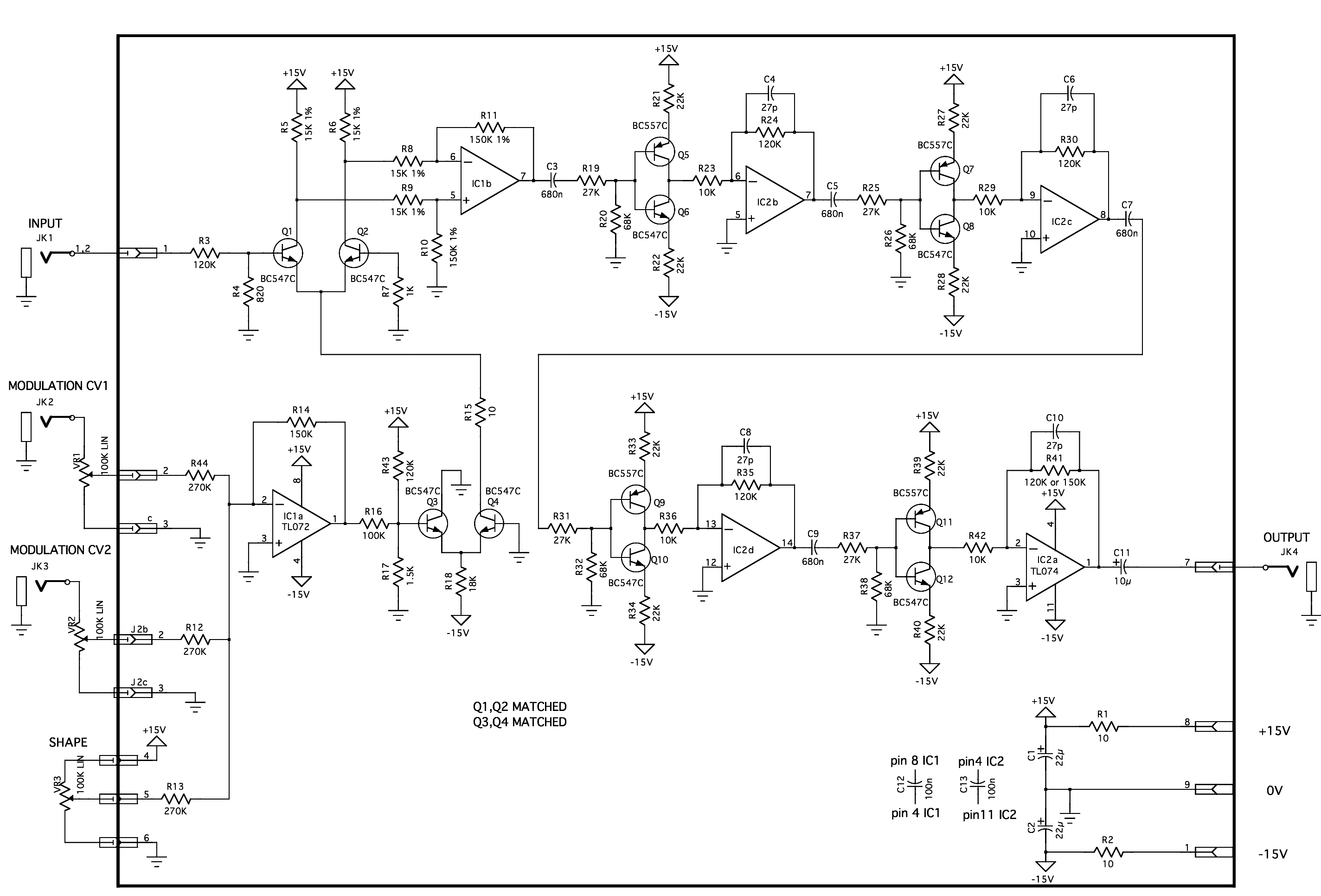
Metalizer-sch.gif
 

(*steve*)

¡sǝpodᴉʇuɐ ǝɥʇ ɹɐǝɥd
Moderator
Calculate the voltage on the base of Q3 from resistors R17 and R43. Changing R43 to 100k may be close enough.

R21/R22 could be changed to 18k (likewise for all the other similar pairs of resistors).

R5 and R6 12k. R18 15k.

Is this for a eurorack mod synth module?
 
Note that the output op-amp is a rail-to-rail device (output can swing to either supply rail) and that if you require the output waveform to reach these levels (for onward voltage-control of anything) then you won't be able to.
 
HI Steve, thanks, it's to go in a music from outer space system I've been building, well actually it is already in the system just i've been noticing some spiralous noises and quite a lot of undulating hum/distorted/noise coming from it at times and realised I hadn't paid enough attention to the fact it was designed to run on a different voltage, lazy really, just assumed it'd be fine..... electronics tends to not like my assumptions :)

"Calculate the voltage on the base of Q3 from resistors R17 and R43"

I hope i'm getting this right, in that i just use a voltage divider calculation?

So here's my calculation based on original component vlaues

15 (v) x 1.5 (R17) = 22.5
120 (R43) + 1.5(R17) =121.5 22.5/121.5 = 0.1851

So the answer 0.1851 needs to remain (or be as close as possible) when adjusting the divider accepting 12v and changing R43?

And with R43 changed to 100K and voltage at 12v

12 (v) x 1.5 (R17) = 18
100 (R43) + 1.5 (R17) = 101.5 18 / 101.5 = 0.1773

Is that close enough?

Actually I stopped here and realized I should be able to calculate, I needed to get some help off a friend though to help me through the steps needed to isolate R43, the calculation needed is;

V source x R17 / V out - R17 = R43

12 x 1.5 / 0.8151 - 1.5 = 95.74

As for the other pairs of resistors, i'm unsure how to calculate these, or at least what calculation is required? Maths is still very new to me, but trying my best to learn and catch up
 
Note that the output op-amp is a rail-to-rail device (output can swing to either supply rail) and that if you require the output waveform to reach these levels (for onward voltage-control of anything) then you won't be able to.

Hey, thanks for your reply

I hope i understand

I don't need the output to reach the peaks to further control anything by voltage, the output is an audio out which usually goes straight into a filter.
 

(*steve*)

¡sǝpodᴉʇuɐ ǝɥʇ ɹɐǝɥd
Moderator
The changed I suggested probably aren't that important. I don't really know why Q3 is biased the way it is, but our of an abundance of caution I'd say keep it as similar as possible.

The values I gave would be what I would start with.
 
I have other Yusynth modules i need to adjust. As I go though them and ask for advice is it best that I post in this thread or separately for each circuit?
 

(*steve*)

¡sǝpodᴉʇuɐ ǝɥʇ ɹɐǝɥd
Moderator
As long as they're all about converting synth modules from +/-15V to +/-12V then I see no problem.

How did the first one go?
 
As long as they're all about converting synth modules from +/-15V to +/-12V then I see no problem.

How did the first one go?

Cheers Steve, yeah i have three more to convert, plus future yusynth builds. It would be good if I can learn to read where reference voltage points (I'm guessing that's what they might be called?) are in the circuits during or by the end of this process and be able to apply some Math to the adjustments required.

I move into a new workshop on Monday, will take me a few days to settle in and set up at which point I can begin changing the resistors. I'll report back as soon as I can with how it has gone.
 
I hadn't thought beyond having a single power supply, the "Music From Out Of Space" modules require +/- 12v, the "Yusynth" modules require +/-15v. I wanted to run them in the same system. Do you think it would be easier to provide both power buses throughout rather than change the modules?
 

Harald Kapp

Moderator
Moderator
You could use a +-15 V power supply plus a pair of 7812/7912 voltage regulators to create the +-12 V for the music module from the +- 15 V. No additional transformer or rectifier required, only the regulators and a handful of capacitors. Easy to wire on a piece of perfboard.
Do you think it would be easier to provide both power buses throughout rather than change the modules?
The additional "bus" is but a pair of wires (ground is and has to be the same for both power systems).
It's the way I'd go because I'm lazy ;D. Doesn't mean you have to do it that way. If you want to learn a bit about modifying ("hacking") the 15 V modules to work from 12 V you're welcome.
 

(*steve*)

¡sǝpodᴉʇuɐ ǝɥʇ ɹɐǝɥd
Moderator
In general there would be no problem supplying some modules with +/-15V and others +/-12V. In fact, most of the modules designed for +/-12V should not be damaged by +/-15V (not a guarantee).

However, a module powered by +/-15V could supply an output voltage outside +/-12V to a module powered by +/-12V, and this might cause problems.

It may be easier to look at the inputs (and outputs) of the +/-12V modules and see if they will be safe in such an instance.

If you go this route, you will need to check any new +/-12V modules, including ones where you don't have the schematic.
 
You could use a +-15 V power supply plus a pair of 7812/7912 voltage regulators to create the +-12 V for the music module from the +- 15 V. No additional transformer or rectifier required, only the regulators and a handful of capacitors. Easy to wire on a piece of perfboard.

The additional "bus" is but a pair of wires (ground is and has to be the same for both power systems).
It's the way I'd go because I'm lazy ;D. Doesn't mean you have to do it that way. If you want to learn a bit about modifying ("hacking") the 15 V modules to work from 12 V you're welcome.

Cheers Harald. Ok, I understand this and agreed it would be easier. I think for now i'm ready to learn how to modify the circuits as it will be a good learning exercise, i'm finding learning Math quite difficult and this might be a good place to begin trying to apply myself more.
 
In general there would be no problem supplying some modules with +/-15V and others +/-12V. In fact, most of the modules designed for +/-12V should not be damaged by +/-15V (not a guarantee).

However, a module powered by +/-15V could supply an output voltage outside +/-12V to a module powered by +/-12V, and this might cause problems.

It may be easier to look at the inputs (and outputs) of the +/-12V modules and see if they will be safe in such an instance.

If you go this route, you will need to check any new +/-12V modules, including ones where you don't have the schematic.

Cheers Steve. Would this mean checking the Control voltage tolerances for each module? Or checking what CV each module expects to recieve? I.m pretty sure the MFOS modules expect -+/-5v and supply this also, I've driven some harder at times by mistake and haven't seen any problems, but then I'm unsure of how over time this might damage the circuit

Also i'm guessing making sure there's no impedance problems between modules?
 

(*steve*)

¡sǝpodᴉʇuɐ ǝɥʇ ɹɐǝɥd
Moderator
Would this mean checking the Control voltage tolerances for each module?

It would mean checking the output voltage for all modules. Make sure it doesn't exceed +/-12V. If the inputs (of the +/- 12V modules) are protected by some series resistance or blocking capacitors then the chance of damage will be reduced.
 
I'd gotten the power distribution incorrect in the entire system. I'd wired it all in series. Rewired it all today with a bus and all noise, spirilous sounds, popping disappeared. If I'd explained the problems I was having with my system and photos of how I'd wired it all I'm sure you'd have pointed my error out straight away. Apologies. I will still make the modifications to the YUSYNTH modules to adapt to +/- 12v. Good news is that my synth now sounds HUGE and wonderful :)
 
Last edited:
Not too make the original post redundant, just I'd thought the problems coming from the synth were because of me not supplying the YUSYNTH modules with the correct power. Works out it was me not getting 'power' correct in the first place.
 
Top