Maker Pro
Maker Pro

Why relay contact stick even when power off?

k49hC39


I have a circuit diagram of fan speed controller(as shown)
some time its work quit normal else the relay contact stick in normally open(NO) contact even
when supply is off(not demagnetize ).
then i hit some object top of the relay, its work normal.
why this sticking issue happens?
relay datasheet
https://img.ozdisan.com/ETicaret_Dosya/445413_4369639.pdf
Thanks
 

Attachments

  • stack.jpg
    stack.jpg
    98.8 KB · Views: 15
Last edited:
Relays can stay closed due to retained magnetism in the pole pieces. I used to repair electric fencers which would have this problem after many cycles. The relays had a brass screw which stopped the pole pieces closing fully. This would wear down after a few years and allow the relay to stick.
 
One other thing with these sealed relays, if used in a clean environment, it pays to vent them.
Some will have a small pip in the corner or centre of the case that can be cut off, they are sealed initially for flux cleaning etc after production.
Using sealed can cause contact erosure or sticking due to ionization occurring internally.
M.
 
Change to a decent size relay perhaps a 10A rated.

If you find it's arcing that is causing the problem, there is a small circuit addition as shown in this video below.

Guess you will never know if the relay is completely blacked out as are current ones.


hevans1944

Hop - AC8NS
What is the purpose of RL1, RL2, and RL4? And what is the purpose of the three RC networks in series between the contacts of these three relays and the "Fan Connector" J2? Why is there no such network of resistors and a capacitor between the contacts of RL3 and the "Fan Connector" J2? Are you really directly applying 230 VAC line voltage to the contacts of RL3 without any contact protection for RL3? Please explain what is going on here.
 
What is the purpose of RL1, RL2, and RL4? And what is the purpose of the three RC networks in series between the contacts of these three relays and the "Fan Connector" J2? Why is there no such network of resistors and a capacitor between the contacts of RL3 and the "Fan Connector" J2? Are you really directly applying 230 VAC line voltage to the contacts of RL3 without any contact protection for RL3? Please explain what is going on here.


when fan is in 1st speed relay RL1 is active other relays are not .
speed relay ON
1 . RL1
2 . RL2
3 . RL4
4 . RL3

RC network in series with relay are used for down the supply voltage(230VAC) with different speed .
How can i protect the contact? please explain..
thanks
 
Last edited:
Greetings Kind Sires . . . .

FWIW . . . . . .

Relevant RELAY INFO . . . .

This is the 12Vdc Coil with its 300VAc / 3A and 750VA contact ratings.
It is the same unit, being used in all 4 relay positions.

https://img.ozdisan.com/ETicaret_Dosya/445413_4369639.pdf

Seems like a NEW relay would be in order for the RL3 position, in regarding highly probable erose and pitting corrupted contact surfaces. Also use a RC snubber across its #2 to 3 contacts, just for INSURANCE..

Re . . . . .? . . . . . What is the purpose of RL1, RL2, and RL4? . . . .?

What I am seeing . . . . . circuit analysis wise . . . . is that initiall activation of logic line R011 causes RL3 to start the motor at full power/speed and then that logic drops off and then . . . . . the activation and holding of either logic line . . . . . . . .

R00 causes relay RL2 to close and the motor runs at LOW speed.
R01 causes relay RL1 to close and the motor runs at MED speed.
R03 causes relay RL4 to close and the motor runs at HIGH speed.

The C3-5 and 7 run capacitors are regulating the motor speed AND serving as "quasi snubbers" . . . as it is . . . for those 3 associated relays.

Presently, the RL3 relay contacts are potentially running "naked".

ADDENDA for . . .
" when fan is in 1st speed relay RL1 is active "
RL1 should be for the MED or 2nd speed


73's de Edd . . . . .

The man who can smile when things go wrong . . . . . has just thought of someone he can blame them on.


Last edited:

hevans1944

Hop - AC8NS
\
How can i protect the contact? please explain..
Read @73's de Edd reply. You need to add a snubber across the relay contacts, or install a new relay, hopefully with better contacts.

An RC snubber is a series-connected resistor and capacitor, placed across normally-open circuit contacts that are closed when you deliver power to the load... a fan motor in your instance. If is only effective with inductive loads (such as fan motors), that store electrical energy in a magnetic field and then release it, rather suddenly, as a current surge when electrical power is removed, i.e., when the circuit contacts open. It is this surge in current as the contacts are opening that cause the arc that eventually damages the relay contacts. You can either eliminate the arcing, use better relay contacts, or do both.

In an RC snubber, the capacitor quickly charges through the low-valued resistor to whatever voltage is developed across the now open contacts to absorb the energy stored in the collapsing magnetic field. The capacitor then releases the energy more slowly through the series snubber resistor and the fan motor winding, thus avoiding the intense arcing that would otherwise occur.

You can look up snubber component values to use in online tables, or try a trial-and-error solution. I would start with an 0.1 microfarad, 600 WVAC plastic film capacitor and a ten ohm, five-watt, metal film resistor. If you can temporarily remove the relay cover to observe any arcing that occurs, it should be easy to adjust the values of the snubber components to eliminate any arcing you see occurring. Good luck with that. You can also substitute a relay with better, heavy-duty, contacts as Edd suggested... assuming you have space available and permission to modify the equipment.
 
\
Read @73's de Edd reply. You need to add a snubber across the relay contacts, or install a new relay, hopefully with better contacts.

An RC snubber is a series-connected resistor and capacitor, placed across normally-open circuit contacts that are closed when you deliver power to the load... a fan motor in your instance. If is only effective with inductive loads (such as fan motors), that store electrical energy in a magnetic field and then release it, rather suddenly, as a current surge when electrical power is removed, i.e., when the circuit contacts open. It is this surge in current as the contacts are opening that cause the arc that eventually damages the relay contacts. You can either eliminate the arcing, use better relay contacts, or do both.

In an RC snubber, the capacitor quickly charges through the low-valued resistor to whatever voltage is developed across the now open contacts to absorb the energy stored in the collapsing magnetic field. The capacitor then releases the energy more slowly through the series snubber resistor and the fan motor winding, thus avoiding the intense arcing that would otherwise occur.

You can look up snubber component values to use in online tables, or try a trial-and-error solution. I would start with an 0.1 microfarad, 600 WVAC plastic film capacitor and a ten ohm, five-watt, metal film resistor. If you can temporarily remove the relay cover to observe any arcing that occurs, it should be easy to adjust the values of the snubber components to eliminate any arcing you see occurring. Good luck with that. You can also substitute a relay with better, heavy-duty, contacts as Edd suggested... assuming you have space available and permission to modify the equipment.

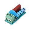
this is the value of scrubber(R and C ) i am taken..is this ok for my circuit?
 

Attachments

  • 3t.jpg
    3t.jpg
    14.6 KB · Views: 7
One other thing with these sealed relays, if used in a clean environment, it pays to vent them.
Some will have a small pip in the corner or centre of the case that can be cut off, they are sealed initially for flux cleaning etc after production.
Using sealed can cause contact erosure or sticking due to ionization occurring internally.
M.
I have wondered about this factor in general (not specific to this topic). What is the standard for "clean"? Many times I have seen various relays in devices which weren't meant for particularly dirty environments yet that nub, or sometimes a piece of tape over a hole instead, was left intact.

For example if the board were to develop a light coating of dust over years of use, is that too dirty to vent it?
 
I always play it safe and open them up, most of the ones I replace are in appliances, oven controls etc, so the environment/air is relatively clean.
I don't think light dust would be a problem, considering how small the vent is usually.
M.
 

Attachments

  • Venting_Sealed_Relays.pdf
    607.6 KB · Views: 1

Harald Kapp

Moderator
Moderator
I always play it safe and open them up
We use millions of electromechanicall relays per year and we never open them. The units we make have a service life of 10 years+.
On the contrary, keeping the relays sealed avoids contact problems in corrosive atmospheres.
 
I'm not so sure 10 years is long enough. I seldom buy anything I intend to use for only 10 years except tech with short lifecycles like phones and computers. Take my furnace for example, the relay on it failed, was soldered on and had a vent hole. I can't recall if it was covered with tape but the replacement relay was. If I had to get a tech out to replace the board, would've easily been a $300 repair for a $10 relay.

Granted I accept that the lifespan of modern *appliances* has shrunk to under 10 years, but none of mine are that young except the air conditioner half of my HVAC.
 

hevans1944

Hop - AC8NS
.is this ok for my circuit?
It is a good set of component values to begin with. How well it works depends on factors, such as fan motor inductance, over which you have no knowledge or control, but give it a try. Make sure the capacitor voltage rating is adequate since it will have full line voltage applied across it when the contacts are open.
 
If this sticking condition was cought early enough on, and contact pitting is negligible, you may be able to just swap relays with one of the other speed outputs and save some money buying another one.

The slow and medium speed outputs use less current and will likely tolerate a relay with contacts that aren't optimal.

I agree a snubber or larger relay is warranted to protect the replacement relay.

It's also possible to help snub the circuit if you can alter (reprogram) the output logic.
Example: Instead of just turning off relay 3, have it quickly ramp down through the other speeds.
 
Top