I am currently studying how Diode Clampers works. (Sorry for the newbie question.)
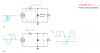
Regarding the picture on the attachment or in this link : https://drive.google.com/file/d/1KqsmmzlFRwVzQ8dE6zRtJlrQ_vh2kQD3/view?usp=sharing. On the result waveform after applying clampling / shifting techniques, I am wondering where did the -0.7 V on the graph came from?
On the negative alternation / half-cycle, the Vp(out) is equal to 0 V as there is no current flowing through the load resistor.
On the positive alternation, the Vp(out) is equal to 2 Vp(in) - 0.7 V through applying KVL : V(in) + V(in) - 0.7 - Vp(out).
As the result, the AC waveform shifted upwards. The Vp(in) - 0.7 V on the graph signifies the new / assumed / considered origin to show that it shifted upwards. I don't know why the -0.7 V is labeled on the peak of the negative alternation, wherein the V(out) is 0 V, hence why it is on the 0 / origin line.
Again, sorry for the newbie question but I will appreciate any help. Thank you.