I recently was helped by the community, so I should pass along some info.
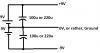
With an op amp circuit and an AC power supply: See picture 1.
The AC power supply's + and - outputs are connected to the power input pins on the op amp. The ground is connected to the circuit ground, which is for connecting ground terminals from speakers, input signals, inverting or non-inverting op amp signal inputs, etc. Take note that an op amp circuit therefore uses three rails, these are +V, -V, and ground/0V.
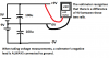
With two DC batteries: See picture 2. (the capacitors are to ensure good operation of the op amp)
Firstly, you take the middle rail to represent ground. This means that whenever you measure a voltage, you compare it to this. So, to measure the top rail's voltage, you compare it to the middle rail. This shows a difference of 9V, so the top rail represents 9V. Next you measure the middle rail's voltage. Since you're comparing it to itself, you'll see a difference of 0V. Lastly, you compare the third rail to the second rail. This is like what you did for the first rail, however instead of comparing a positive terminal's output to ground, you are comparing a negative voltage to ground. The result: you'll see a difference of -9V.
Use this circuit to power op amps if you have no AC sources available!
NOTE: I forgot to re-draw the voltmeter display screen. Sorry!
 just reverse the two leads of positive supply and u get negative ?